 KPMI


Articles
- Page Path
- HOME > J Powder Mater > Volume 33(5); 2026 > Article
-
Research Article
- Phase-Equilibrium-Guided Carbonyl Processing of Highly Active Nickel Powders
- Seoung Uk Bae1,2, Kyoung-Tae Park1, Joo Hyun Park2, Jae Hong Shin1,*
-
Journal of Powder Materials 2026;33(5):338-347.
DOI: https://doi.org/10.4150/jpm.2026.00185
Published online: October 31, 2026
1Korea National Institute of Rare Metals, Korea Institute of Industrial Technology, Incheon 21655, Republic of Korea
2Department of Materials Science and Chemical Engineering, Hanyang University, Ansan 15588, Republic of Korea
- *Corresponding author: Jae Hong Shin shinclusion@kitech.re.kr
© The Korean Powder Metallurgy & Materials Institute
This is an Open Access article distributed under the terms of the Creative Commons Attribution Non-Commercial License (http://creativecommons.org/licenses/by-nc/4.0/) which permits unrestricted non-commercial use, distribution, and reproduction in any medium, provided the original work is properly cited.
- 177 Views
- 6 Download

Abstract
- Nickel powders with large specific surface areas are cost-effective alternatives to noble-metal catalysts for hydrogen-producing reactions, including methane reforming and ammonia decomposition. However, thermodynamic control of nickel carbonyl formation and decomposition is essential for producing catalytically active powders through the Mond process. In this study, we established a thermodynamic framework for carbonyl nickel production by combining Gibbs free-energy analysis, the Clausius–Clapeyron relation, and liquid–gas phase-equilibrium calculations for the reaction Ni + 4CO ↔ Ni(CO)₄. The resulting phase-equilibrium map identified operating windows for selective nickel carbonyl formation and subsequent decomposition. High-pressure carbonylation achieved 99.7% nickel conversion at 200 °C and 50 atm, whereas thermal decomposition at 300 °C and 1 atm yielded 57.9% nickel recovery. Scanning electron microscopy revealed needle-like nickel particles, suggesting a morphology favorable for catalytic applications. Process simulations captured pressure evolution and Ni(CO)₄ phase transitions, supporting rational selection between liquid- and gas-phase operating regimes. These findings indicate that phase-equilibrium-guided carbonyl processing offers a scalable route to high-activity nickel powder catalysts for hydrogen-production technologies.
- Methane is both an important industrial feedstock and a major greenhouse gas, representing the second-largest contributor to climate change after CO2. Approximately 28% of total methane emissions originate from natural gas and petroleum systems [1]. At the same time, methane-based natural gas reforming accounts for about 49% of global hydrogen production, and natural gas remains a primary feedstock for gray, blue and turquoise hydrogen production [2-4]. Methane reforming therefore occupies a critical position at the interface of carbon management and hydrogen technologies. In this process, catalysts are essential for improving methane conversion, hydrogen yield and reaction selectivity, while suppressing byproduct formation, sintering and carbon deposition [4-11]. Platinum-group catalysts can satisfy many of these performance requirements, but their high cost and limited availability remain major barriers to large-scale hydrogen-production applications [12].
- Nickel is a critical metal widely used in catalysis, energy conversion and electronic materials [13]. Among nickel-based materials, carbonyl nickel has attracted particular attention because of its much larger specific surface area than conventional spherical nickel powders, which can provide abundant active sites and high catalytic activity [14]. These characteristics make carbonyl nickel a promising alternative to expensive Pd- and Pt-based catalysts for hydrogen-producing reactions such as methane reforming and ammonia decomposition [15,16]. As the demand for efficient hydrogen-production technologies increases, the development of nickel catalysts that maintain high activity and stability under reforming conditions has become increasingly important [17].
- High-activity carbonyl nickel is produced through the Mond process, discovered in the late nineteenth century, which is based on the reversible reaction between nickel and carbon monoxide (Ni + 4CO ⇌ Ni(CO)4) [18].
- In this process, nickel tetracarbonyl, Ni(CO)4, acts as a volatile transport intermediate that forms under carbonylation conditions and decomposes at elevated temperature to yield high-purity nickel. The carbonyl process can therefore be regarded as a chemical vapor transport and refining cycle governed by temperature, pressure, carbon monoxide partial pressure and nickel surface activity [19, 20]. Ni(CO)4 formation is favored at relatively low temperatures, typically 45–120 °C, whereas decomposition becomes dominant at higher temperatures, making thermodynamic control essential for determining conversion efficiency and product characteristics [21]. Beyond catalytic applications, the carbonyl process has long been used industrially for nickel refining and powder production, supplying high-purity nickel powders with distinctive morphologies for powder metallurgy, coatings and catalytic uses [21,22]. More recently, demand for high-activity nickel powders has expanded to emerging applications including nanomaterials, battery electrodes and advanced catalysts [23-26]. Carbonyl nickel, with its high surface area and favorable morphology, is therefore a strong candidate for these applications [24].
- Previous studies on carbonyl nickel production have primarily focused on process equipment development, empirical operation and specific mechanistic aspects of Ni(CO)4 formation and decomposition [21,27-32]. Windsor et al. examined the fundamental mechanism of Ni(CO)4 formation by clarifying the roles of surface activation and sulfur-containing species [30], while Podall established thermodynamic principles for metal–CO bond formation and the conceptual basis of carbonyl reactions [29]. Nametkin et al. further reported ligand-substitution behavior in metal carbonyls, providing insight into CO-bond stability and reaction selectivity [32]. Liang et al. experimentally identified Ni subcarbonyl intermediates on nickel surfaces, indicating that Ni(CO)4 formation proceeds through sequential molecular steps [31]. Wang et al. demonstrated that H₂S-induced surface activation markedly enhances the rate and efficiency of Ni(CO)4 formation [27], while Terekhov et al. proposed a carbonyl-based extraction process for laterite ores and discussed operational pressure conditions [28]. Shu et al. analyzed the effect of elevated pressure on the Ni(CO)4–Fe(CO)5 equilibrium in industrial carbonyl systems, highlighting the importance of controlled separation during high-pressure operation [21]. Despite these advances, a systematic framework linking Gibbs free-energy changes, phase-equilibrium behavior, pressure evolution and operational mode selection remains limited. In particular, the implications of Ni(CO)4 liquid–gas phase transitions for selecting liquid- or gas-phase operating conditions have not been sufficiently established.
- Here, we develop a thermodynamic and phase-equilibrium framework for carbonyl nickel production aimed at producing high-activity nickel powder catalysts for hydrogen-production reactions. Gibbs free-energy calculations and Clausius–Clapeyron analysis are used to define the formation and decomposition boundaries of Ni(CO)4, while high-pressure carbonylation and decomposition experiments validate the predicted operating windows. Process simulations are further combined with the thermodynamic analysis to examine pressure evolution and Ni(CO)4 phase transitions during reaction. This integrated approach provides a rational basis for selecting liquid- or gas-phase carbonyl-process conditions and offers a scalable route for producing high-activity nickel powders as cost-effective catalyst materials for hydrogen-production technologies.
1. Introduction
- High-purity nickel powder was used as the starting material. Approximately 1 g of nickel powder was placed in an alumina boat and introduced into the reaction chamber. Before carbonylation, the powder was pretreated under flowing high-purity hydrogen gas to remove surface oxides and activate the nickel surface. The pretreatment was conducted at 400 °C for 1 h under 99.999% H₂ flowing at 1 L/ min.
- The carbonylation experiments were carried out using a high-pressure reaction system installed in a horizontal tubular furnace, as schematically shown in Fig. 1. The reaction chamber was fabricated from SUS316 stainless steel and designed for operation up to 50 atm. The internal pressure was controlled using a downstream pressure-regulation unit to ensure stable high-pressure operation. Nickel tetracarbonyl generated during carbonylation was transported through a heated connection line to a downstream decomposition chamber, which was independently temperature-controlled for subsequent thermal decomposition of Ni(CO)4.
- Carbonylation was performed at 200 °C under two pressure conditions, 1 and 50 atm. Specifically, the low-pressure carbonylation experiments were performed at 1 atm and 50 °C for 36 and 60 h, whereas the high-pressure experiment was performed at 50 atm and 200 °C for 3 h. After reaction, the residual nickel powder remaining in the alumina boat was weighed and compared with the initial nickel loading. The carbonylation rate was calculated as:
- Where, Wi is the initial nickel mass and Wf is the residual mass after reaction.
- Following carbonylation, the generated Ni(CO)₄ gas was introduced into the decomposition chamber and thermally decomposed at 300 °C under 1 atm. The recovered nickel powder was collected and weighed to determine the nickel recovery yield.
- And the nickel recovery rate after thermal decomposition was calculated as:
- Where, WP is the recovered nickel powder mass after thermal decomposition.
- The morphology of the recovered nickel powder was examined by field-emission scanning electron microscopy, FE-SEM, using a JSM-7100F instrument, JEOL. The particle-size distribution was measured by dynamic light scattering, DLS, using an ELS-Z2 instrument, Otsuka Electronics. These analyses were used to evaluate the effects of carbonylation pressure and decomposition conditions on the morphology and particle-size characteristics of the nickel powder.
2. Experimental methods
- 3.1 Thermodynamic calculations
- The carbonylation reaction of nickel is represented by Eq. (3):
- To perform the thermodynamic calculations for Eq. (3), the commercial thermodynamic software FactSage 8.0 was employed. The FactPS thermodynamic database was used, and Gibbs free energy changes (ΔG) were calculated as a function of temperature under selected pressure conditions. The pressure values used in the Gibbs free-energy calculations represent the specified system pressure under a CO atmosphere, and condensed metallic Ni was treated as a pure phase.
- As shown in Fig. 2, the equilibrium temperature was found to increase with increasing pressure. At 1 atm, the carbonylation reaction proceeds favorably below 121.2℃, whereas at 10 atm and 100 atm, the equilibrium temperatures were estimated to be around 187.2℃ and 289.2℃, respectively. This result indicates that higher pressures allow the reaction to proceed at elevated temperatures while still maintaining thermodynamic stability. Accordingly, pressure can be identified as a critical variable in determining the optimal conditions for the nickel carbonylation process.
- To determine the boundary temperature at which the forward carbonylation reaction of nickel and the reverse decomposition of nickel tetracarbonyl (Ni(CO)₄ → Ni + 4CO) occur under different pressures, a pressure–temperature (P–T) diagram was calculated, as shown in Fig. 3.
- In the diagram, the region below the red line corresponds to the stability domain of Eq. (3) in the forward direction, where nickel reacts with carbon monoxide to form Ni(CO)₄. Conversely, the region above the red line represents the conditions under which Eq. (3) proceeds in the reverse direction, meaning that Ni(CO)₄ decomposes into metallic nickel and carbon monoxide.
- This analysis clearly illustrates the thermodynamic boundary between the formation and decomposition regimes of Ni(CO)₄, providing essential information for selecting appropriate operating conditions in the carbonyl process.
- 3.2 Phase Equilibrium Analysis
- To establish a clear understanding of the carbonyl process and to derive appropriate operating conditions, it is essential to consider not only the thermodynamics of the carbonylation reaction but also the phase equilibrium of nickel tetracarbonyl (Ni(CO)₄). Determining the liquid–vapor phase boundary of Ni(CO)₄ requires calculation of its saturation vapor pressure.
- In this study, the Clausius–Clapeyron equation Eq. (4) was applied to describe the relationship between temperature and vapor pressure.
- Where, P (atm) is pressure, T (K) is temperature, ∆Hvap (kJ/mol) is enthalpy change of vaporization and ∆V (L) is molar volume change.
- By combining Eq. (3) with the ideal gas law (PV=nRT), the expression can be rewritten as Eq. (5).
- By combining Eqs. (4) and (5) and integrating, the relationship expressed in Eq. (6) is obtained, which allows the calculation of the saturation vapor pressure of Ni(CO)4 as a function of temperature.
- Where pvap is the vapor pressure at a given temperature and C is the integration constant. The integration constant C was determined by substituting the saturation vapor pressure (P) value and the enthalpy of vaporization (∆Hvap) at the boiling point of Ni(CO)₄ (315.48 K), resulting in a value of 11.17. This value obtained when the vapor pressure (P) is expressed in atm and the temperature is expressed in K
- The vapor phase was approximated as an ideal gas, and the molar volume of the liquid phase was assumed to be negligible compared with that of the vapor phase.
- In addition, ∆Hvap was treated as approximately temperature-independent over the investigated range for the purpose of the integrated Clausius–Clapeyron calculation.
- The necessary thermodynamic parameters for these calculations were obtained from the FactSage 8.0 database, and the computation results are presented in Fig. 4.
- As shown in Fig. 4, the green line represents the calculated phase boundary. Below this line, Ni(CO)₄ is thermodynamically stable in the liquid state, whereas above the line, it is stable in the gaseous state. To validate the accuracy of this prediction, the calculated vapor pressure curve was compared with experimental data reported in the literature [33]. The comparison confirmed good agreement between the calculated results and previously reported measurements, indicating the reliability of the present approach.
- By superimposing the calculated Ni(CO)₄ phase boundary with the pressure–temperature (P–T) diagram of the carbonylation reaction (Fig. 3), a comprehensive thermodynamic phase diagram of the carbonyl nickel process was obtained, as shown in Fig. 5.
- This diagram delineates three distinct regions. The blue region corresponds to conditions where the carbonylation reaction proceeds and the generated Ni(CO)4 exists as a liquid. The yellow region represents conditions where the carbonylation reaction occurs, but Ni(CO)4 remains in the gas phase. In contrast, the red region indicates conditions above the decomposition boundary, where Ni(CO)4 is thermodynamically unstable and decomposes into metallic nickel and carbon monoxide.
- This integrated phase equilibrium diagram thus provides a valuable framework for selecting optimal operating conditions in the carbonyl process, allowing distinction between liquid-phase and gas-phase operation as well as identifying the stability region of nickel.
- The red points shown in Fig. 5 will be discussed in detail in the subsequent section on the application of the thermodynamic phase diagram.
- 3.3 Application of the Thermodynamic Phase Diagram
- Assuming that the carbonyl nickel process is carried out under the conditions summarized in Table 1, the pressure variation inside the reaction chamber as a function of conversion (Rt/R0, where Rt is amount of reacted Ni powder and R0 is initial amount of Ni powder) can be illustrated as shown in Fig. 6.
- When the carbonylation reaction proceeds in a closed system, as expressed by Eq. (2), four moles of CO react with nickel to form one mole of Ni(CO)4. Consequently, the total number of gas moles decreases as the reaction progresses, leading to a gradual reduction in the chamber pressure with increasing conversion.
- The red points indicated in Fig. 5 represent the pressure behavior mapped onto the phase diagram as the reaction proceeds from point a to point e, corresponding to increasing conversion. Based on this, Fig. 7 schematically depicts the expected phenomena within the reaction chamber as a function of reaction progress. Taken together, Figs. 5–7 provide a comprehensive interpretation of the thermodynamic and phase behavior during the carbonylation process.
- At the initial condition (point a), liquid Ni(CO)4 formation is thermodynamically stable, and thus liquid Ni(CO)4 accumulates as the reaction proceeds. At approximately 20% conversion (point c), the system reaches the boundary between the liquid and gas stability regions. At this stage, the previously formed liquid Ni(CO)4 begins to vaporize, resulting in coexistence of both liquid and gaseous Ni(CO)4. At point c, the system reaches the liquid–gas phase boundary of Ni(CO)4. As the previously formed liquid Ni(CO)4 begins to vaporize, the number of moles in the gas phase increases temporarily, producing the small pressure rise shown in Fig. 6. After entering the gas-phase stability region, gaseous Ni(CO)4 remains in the gas phase, and the net decrease in gas-phase moles becomes smaller because four moles of CO are consumed while one mole of gaseous Ni(CO)4 is generated. With further conversion, the system reaches point d, where the pressure has decreased sufficiently to fall into the gaseous stability region. Under these conditions, Ni reacts directly with CO to produce gaseous Ni(CO)4.
- Finally, at the completion of the reaction (point e), the pressure decreases to approximately 25 atm and the chamber contains a mixture of gaseous Ni(CO)4 and unreacted excess CO. This analysis indicates that, although liquid Ni(CO)4 is transiently generated during the reaction course, it ultimately disappears, leaving Ni(CO)4 in the gaseous phase as the final stable product together with residual carbon monoxide.
- 3.4 Experimental results of carbonyl process
- Fig. 8 shows the carbonylation rates obtained under different reaction conditions. At 1 atm and 50℃, the carbonylation rates were only 5% and 9% even after prolonged reaction times of 36 h and 60 h, respectively, indicating that the reaction hardly proceeded under low-temperature and low-pressure conditions. In contrast, under 50 atm and 200℃, the carbonylation rate sharply increased to 99.7% within just 3 h, clearly demonstrating that the carbonylation reaction is highly promoted under high-pressure and elevated-temperature conditions. These results highlight the critical role of temperature and pressure as key parameters governing the reaction efficiency in the carbonyl process.
- Fig. 9 shows photographs of the alumina boat before and after the carbonylation experiment conducted at 50 atm and 200℃. In (a), the nickel powder was loaded under dry conditions, and both the alumina boat and the nickel powder remained in a dry state prior to the reaction. In contrast, (b) depicts the alumina boat after the reaction, where residual nickel powder remained. As highlighted by the red circle, wetting traces were observed, indicating the presence of a transient liquid phase. This observation is consistent with the prediction from the phase equilibrium analysis, which suggested that liquid Ni(CO)₄ can be temporarily formed during the carbonylation reaction.
- After the carbonylation reaction, the generated Ni(CO)4 was transferred to the decomposition chamber and thermally decomposed at 300℃ and 1 atm, resulting in the formation of nickel powder. In addition, the 57.9% nickel recovery obtained after decomposition at 300 °C and 1 atm. The powder nucleated and grew on the inner wall of the decomposition chamber and was subsequently collected for characterization. A small amount of Ni(CO)₄ may also have been transported beyond the principal decomposition/collection region. This is presumed to be the reason for the low nickel recovery rate of 57.9%. The particle size distribution of the recovered nickel powder which obtained by DLS analysis is shown in Fig. 10. The DLS result as an equivalent hydrodynamic diameter rather than the direct physical diameter of the individual needle-like particles. The DLS-derived D50 value reflects the light-scattering behavior of dispersed particles/agglomerates and therefore may differ from the actual dimensions observed by SEM. The powder exhibited a narrow distribution centered around an average particle size of approximately 126.8 nm, suggesting that the reaction conditions in the carbonyl process were relatively well controlled.
- Fig. 11 presents scanning electron microscopy (SEM) images of the carbonyl nickel powder recovered from the decomposition chamber.
- At low magnification (top), the nickel particles are observed to form entangled, needle-like structures, with individual particles agglomerating into elongated chain morphologies. Higher-magnification images (bottom) reveal that the particle surfaces are not smooth but instead exhibit irregular projections and rough textures. This non-uniform morphology provides a significantly increased specific surface area, which is a characteristic feature of carbonyl nickel powders.
3. Results and Discussion
- This study establishes a thermodynamic and phase-equilibrium framework for optimizing the carbonyl nickel process and demonstrates its experimental relevance for producing high-activity nickel powders. Gibbs free-energy calculations combined with the Clausius–Clapeyron relation defined the formation and decomposition boundaries of Ni(CO)4 and distinguished the stability domains of liquid and gaseous Ni(CO)4. The calculated phase behavior shows that the equilibrium temperature increases with pressure, enabling the selection of liquid- or gas-phase operating regimes for carbonyl processing.
- By integrating the phase-equilibrium map with reaction conversion, the pressure evolution and phase transitions inside the reaction chamber were further clarified. The analysis indicates that liquid Ni(CO)4 can form transiently during the early stage of carbonylation and subsequently transition to the gas phase as the reaction proceeds. Wetting traces observed on the alumina boat after reaction provide experimental evidence supporting this predicted transient liquid-phase formation.
- High-pressure carbonylation experiments confirmed the decisive role of pressure and temperature in Ni(CO)4 formation. At 200 °C and 50 atm, a carbonylation rate of 99.7% was achieved within 3 h, whereas low-pressure operation at 1 atm and 50 °C resulted in only 5–9% conversion even after extended reaction times. Subsequent decomposition at 300 °C and 1 atm produced nickel powders with a relatively narrow particle-size distribution centered at 126.8 nm. SEM observations revealed needle-like, chain-shaped agglomerates with rough and irregular surfaces, indicating morphological features that can increase the accessible surface area and contribute to the high catalytic activity of carbonyl nickel powders.
- Together, these findings show that thermodynamically guided control of Ni(CO)4 formation, phase transition and decomposition provides a rational basis for carbonyl-process design. The results demonstrate a feasible route for producing high-activity nickel powders and highlight their potential as cost-effective catalyst materials for hydrogen-production reactions, as well as for broader powder metallurgy and advanced materials applications.
4. Conclusion
-
Funding
This work was supported by the Technology Innovation Program (Industrial Strategic Technology Development Program) (00469049, Development of Carbonyl Process for Producing Highly Active Nickel Powder with a Specific Surface Area 7,000 cm2/g from Nickel Compound), funded By the Ministry of Trade, Industry & Energy (MOTIE), Korea.
-
Conflict of Interest
The authors declare no conflict of interest.
-
Data Availability Statement
The data supporting the findings of this study are available from the corresponding author upon reasonable request.
-
Author Information and Contribution
Seoung Uk Bae: Writing-Original draft preparation, Investigation, Data curation, and Validation. Kyoung-Tae Park: Reviewing. Joo Hyun Park: Reviewing and Editing. Jae Hong Shin: Resources, Supervision, Project administration, Writing, Reviewing, and Editing. All the authors have read and agreed to the published version of the manuscript.
-
Acknowledgments
None.
Article information


| Conditions | Value |
|---|---|
| Reactor volume | 80 L |
| Amount of initial Ni powder | 1 kg |
| Reaction temperature | 200 ℃ |
| Excess CO gas | 150% of the stoichiometric requirement |
- 1. M. Filonchyk, M, M. P. Peterson, L. Zhang, L, V. Hurynovich and Y. He: Sci Total Environ., 935 (2024) 173359.Article
- 2. A. Gupta, R. Kumar, J. P. Sharma, M. H. Ahmadi, J. Najser, V. Blazek and L. Prokop: J Therm. Anal., 149 (2024) 14517.ArticlePDF
- 3. F. Pruvost, S. Cloete, C. A. del Pozo and A. Zaabout: Energy Convers Manag., 274 (2022) 116458.Article
- 4. S. S. Kumar and H. Lim: Energy Rep., 8 (2022) 13793.Article
- 5. S. Rakass, H. Oudghiri-Hassani, P. Rowntree and N. Abatzoglou: J. Power Sources., 158 (2006) 485.Article
- 6. A. Fonseca and E. M. Assaf: J. Power Sources., 142 (2005) 154.Article
- 7. L. Chen, Z. Qi, S. Zhang, J. Su and G. A. Somorjai: Catalysts, 10 (2020) 858.Article
- 8. S. N. Miskan, B. A. Abdulkadir, N. Ainirazali, A. A. Jalil, J. W. Lim and H. D. Setiabudi: Int. J. Hydrogen Energy, 104 (2025) 302.Article
- 9. M. Yusuf, A. S. Farooqi, A. A. Al-Kahtani, M. Ubaidullah, M. A. Alam, L. K. Keong, K. Hellgardt and B. Abdullah: Int. J. Hydrogen Energy, 46 (2021) 27044.Article
- 10. C. Wan, Z. Shi, M. Huang, J. Pan, R. Luo, D. Li and L. Jiang: Int. J. Hydrogen Energy, 46 (2021) 3833.Article
- 11. Y. S. Noh, K. Y. Lee and D. J. Moon: Int. J. Hydrogen Energy, 44 (2019) 21010.Article
- 12. U. Tang, Z. Peng, R. Tian, L. Ye, J. Zhang, M. Rao and G. Li: J. Environ. Chem. Eng., 11 (2023) 110237.Article
- 13. S. De, J. Zhang, R. Luque and N. Yan: Energy Environ. Sci., 9 (2016) 3314.Article
- 14. O. S. Makarenko and O. I. Hetman: Powder Metall. Met. Ceram., 62 (2024) 633.ArticlePDF
- 15. B. O. Yusuf, M. Umar, E. Kotob, A. Abdulhakam, O. A. Taialla, M. M. Awad, I. Hussain, K. R. Alhooshani and S. A. Ganiyu: Chem. Asian J., 19 (2024) 1.Article
- 16. V. M. Gonzalez-Delacruz, R. Pereniguez, F. Ternero, J. P. Holgado and A. Caballero: ACS Catalysis, 1 (2011) 82.Article
- 17. S. Li and J. Gong: Chem. Soc. Rev., 43 (2014) 7245.Article
- 18. L. Mond, C. Langer and F. Quincke: J. Chem. Soc., 57 (1890) 749.Article
- 19. J. Das, S. Srikanth and Premchand: Proc. Int. Conference on Recent Advances in Metallurgical Processes, (2013) 171.
- 20. M. Schmitt, M. Mayländer, J. Goost, S. Richert and I. Krossing: Angew. Chem. Int. Ed., 60 (2021) 14800.ArticlePDF
- 21. J. Shu and L. Koehler: Powder Metall. Rev., 6 (2017) 39.
- 22. A. E. Wallis: US2159412A, (Patent).
- 23. N.-D. Jaji, H. L. Lee, M. H. Hussin, H. M. Akil, M. R. Zakaria and M. B. H. Othman: Nanotechnol. Rev., 9 (2020) 1456.Article
- 24. A. Helal, S. S. Shah, M. Usman, M. Y. Khan, M. A. Aziz and M. M. Rahman: Chem. Rec., 22 (2022) e202200055.Article
- 25. F. Guo, Q. Chen, Z. Liu, D. Cheng, N. Han and Z. Chen: Catalysts, 13 (2023) 1241.Article
- 26. D. Zhou, X. Guo, Q. Zhang, Y. Shi, H. Zhang, C. Yu and H. Pang: Adv. Funct. Mater., 32 (2022) 2107928.Article
- 27. D. Wang, A. Chen, Z. Zhao and G. Huo: Transit. Met. Chem., 34 (2009) 313.ArticlePDF
- 28. D. S. Terekhov and N. V. Emmanuel: Miner. Eng., 54 (2013) 124.Article
- 29. H. E. Podall: J. Chem. Edu., 38 (1961) 187.Article
- 30. M. M. Windsor and A. A. Blanchard: J. Am. Chem. Soc., 55 (1933) 1877.Article
- 31. D. B. Liang, G. Abend, J. H. Block and N. Kruse: Surf. Sci., 126 (1983) 392.Article
- 32. N. S. Nametkin, V. D. Tyurin, A. I. Nekhaev, M. Mavlonov and M. A. Kukina: Russ. Chem. Bull., 24 (1975) 2739.ArticlePDF
- 33. J. Dewar and H. O. Jones: Proceedings of the Royal Society of London, 71 (1903) 467.Article
References
Figure & Data
References
Citations

 ePub Link
 Cite this Article
 XML Download
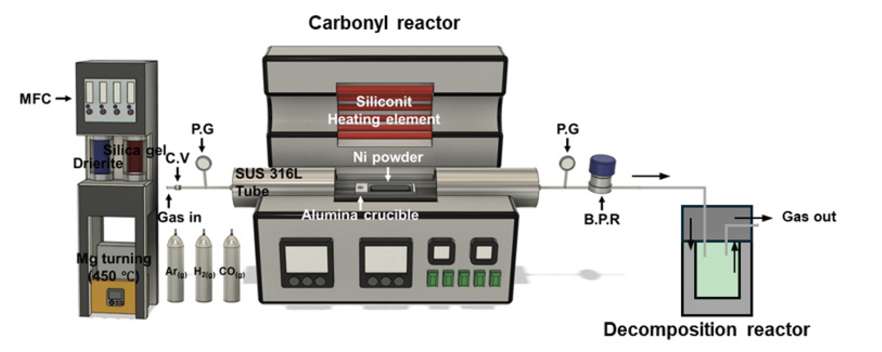
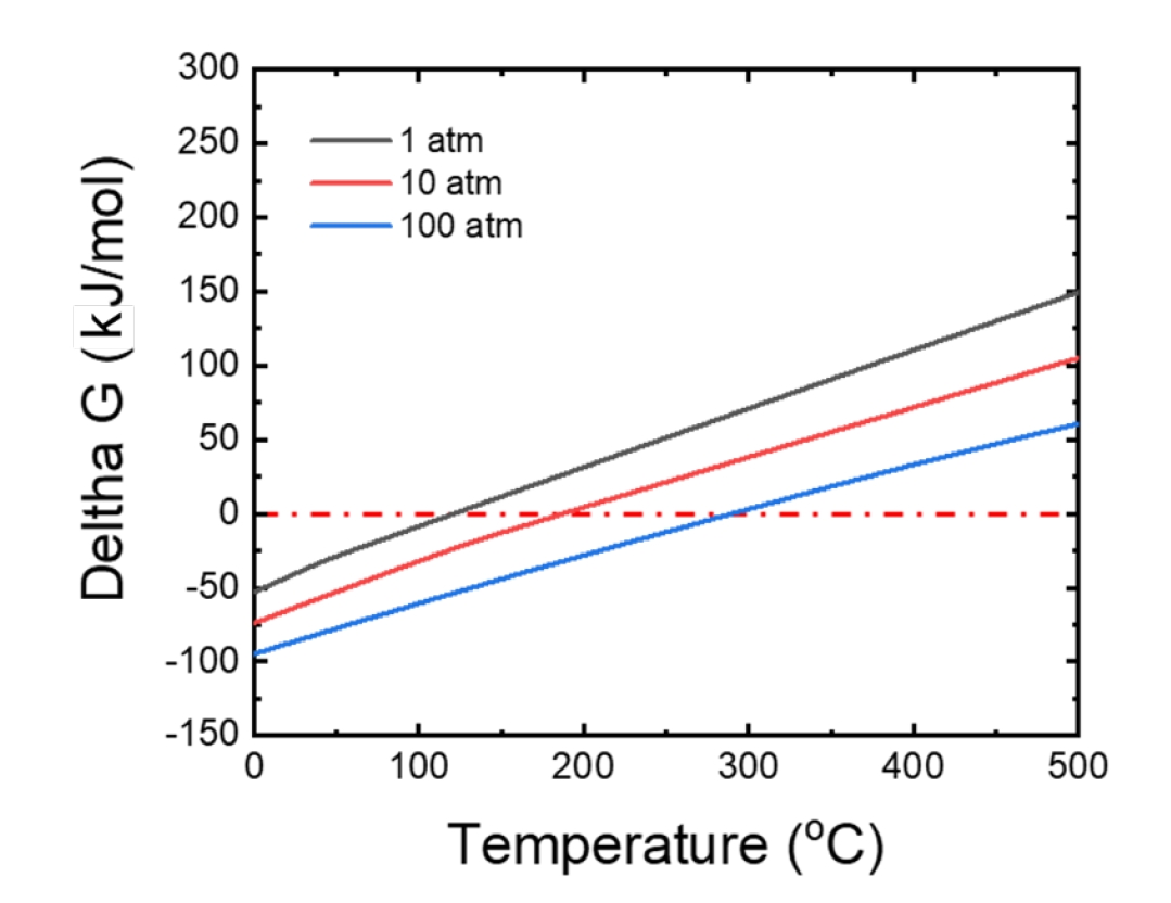
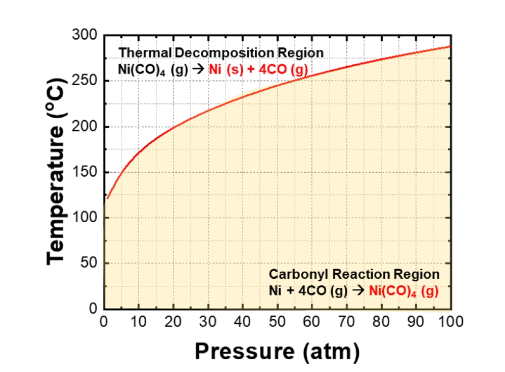
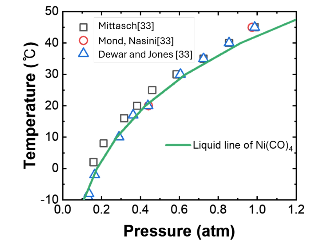
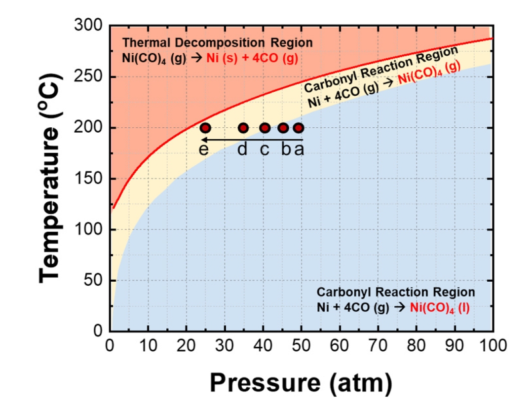
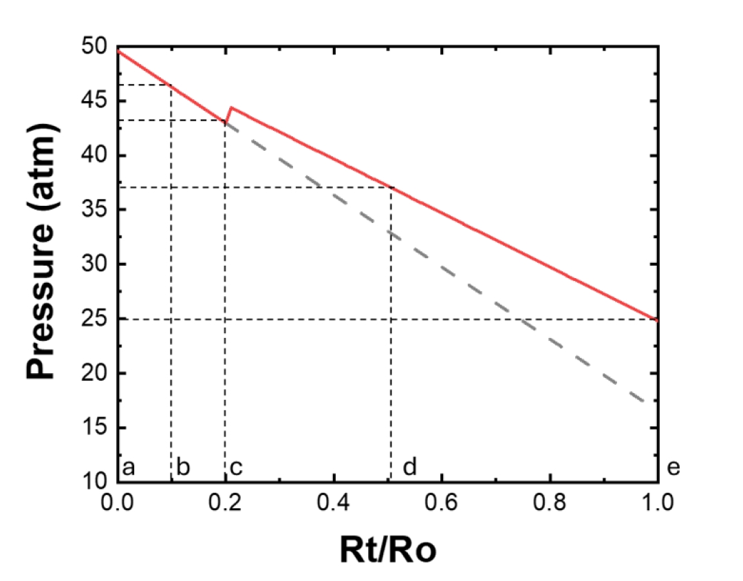
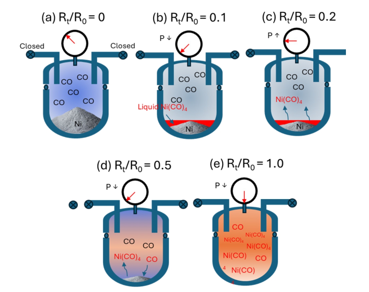
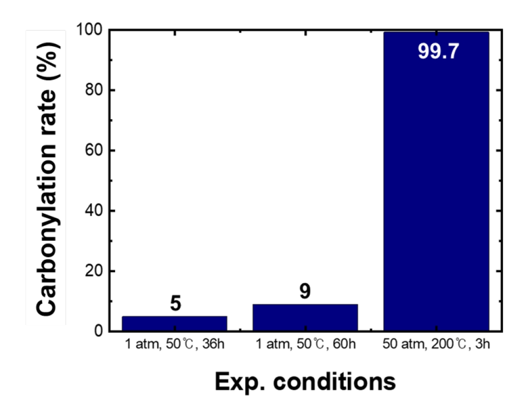
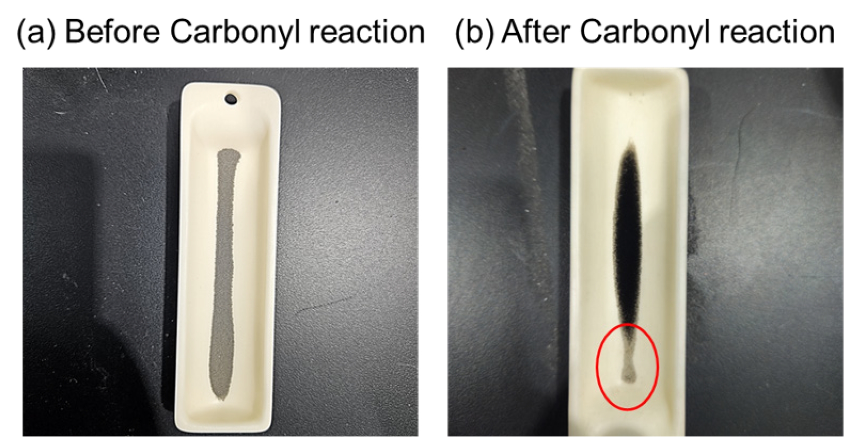
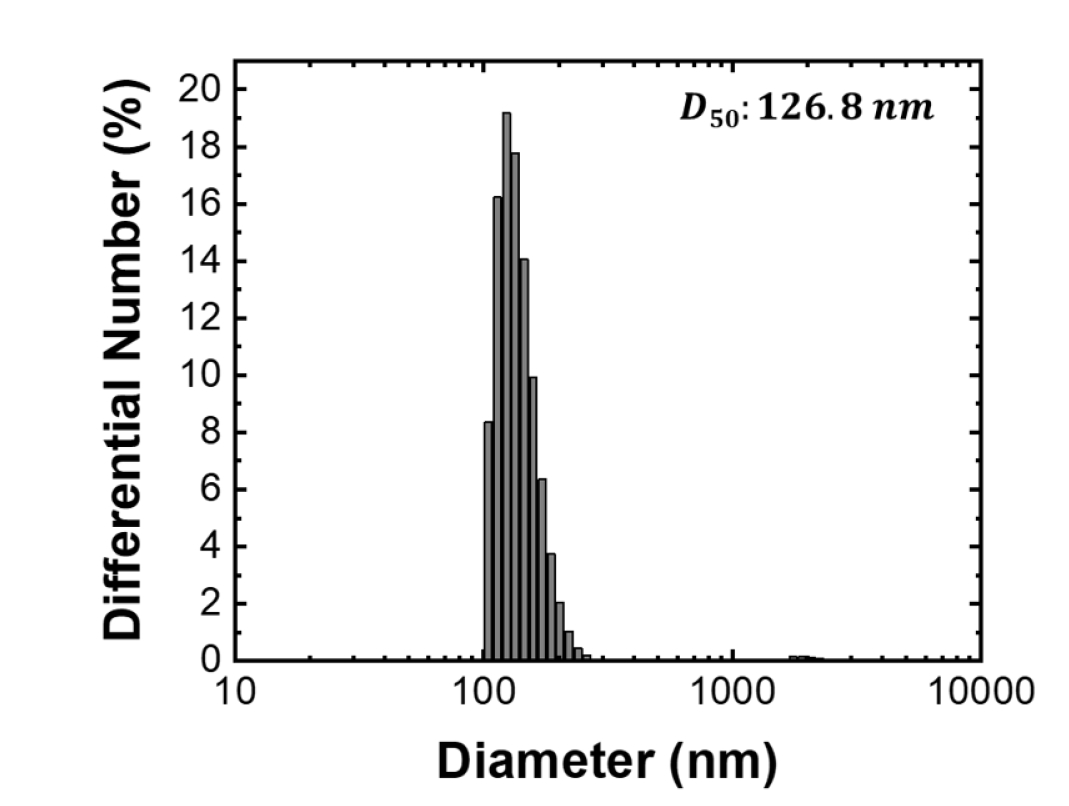
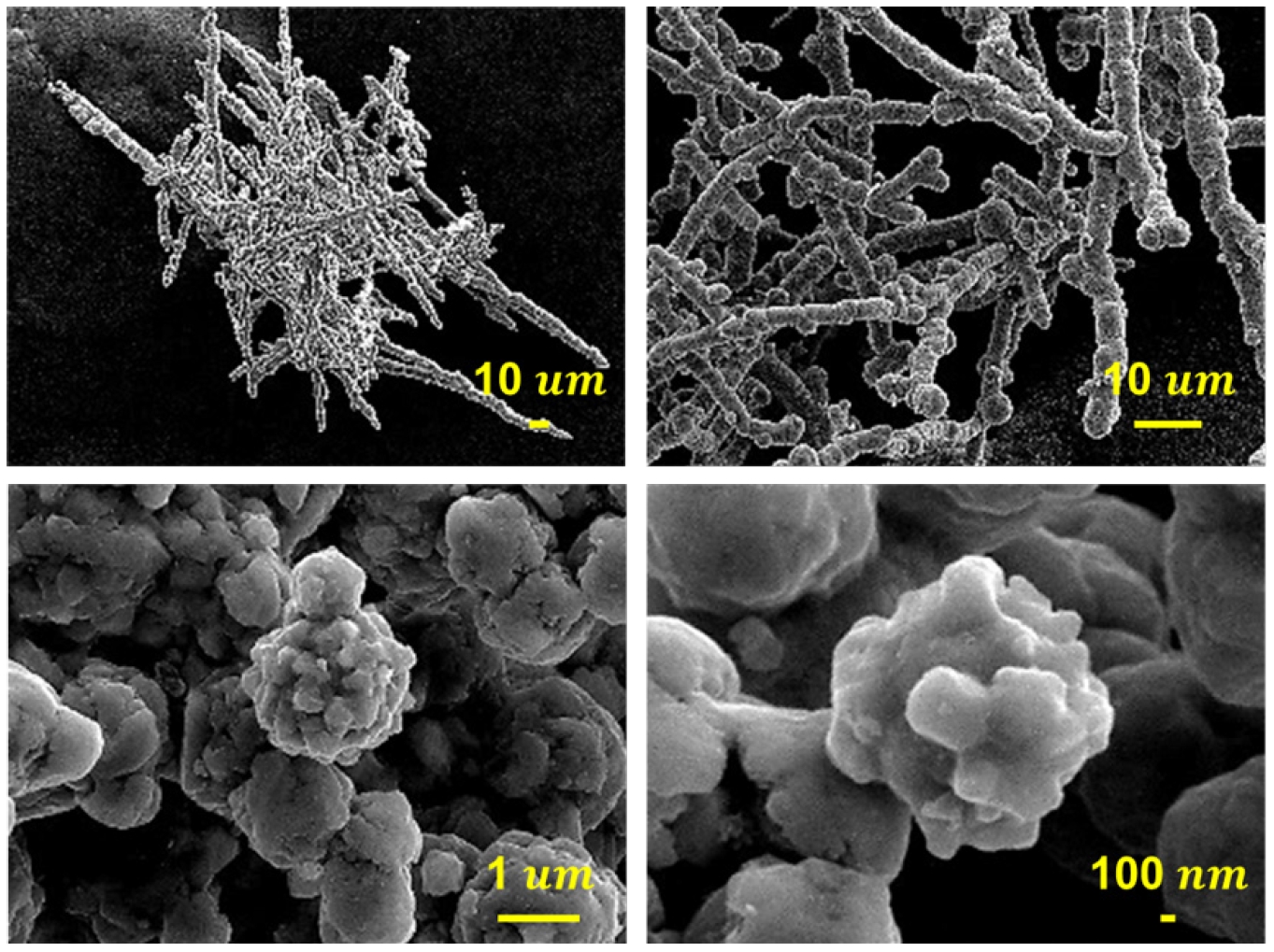
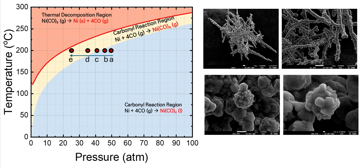
Fig. 1.
Fig. 2.
Fig. 3.
Fig. 4.
Fig. 5.
Fig. 6.
Fig. 7.
Fig. 8.
Fig. 9.
Fig. 10.
Fig. 11.
Graphical abstract
| Conditions | Value |
|---|---|
| Reactor volume | 80 L |
| Amount of initial Ni powder | 1 kg |
| Reaction temperature | 200 ℃ |
| Excess CO gas | 150% of the stoichiometric requirement |
Table 1.
TOP

