Articles
- Page Path
- HOME > J Korean Powder Metall Inst > Volume 24(5); 2017 > Article
-
ARTICLE
- Fabrication and Characterization of Thermal Battery using Porous MgO Separator Infiltrated with Li based Molten Salts
- Kyungho Kim, Sungmin Lee, Chae-Nam Ima, Seung-Ho Kanga, Hae-Won Cheonga, Yoonsoo Han*
-
Journal of Korean Powder Metallurgy Institute 2017;24(5):364-369.
DOI: https://doi.org/10.4150/KPMI.2017.24.5.364
Published online: September 30, 2017
Engineering Ceramic Center, Korea Institute of Ceramic Engineering and Technology, Icheon 17303, Republic of Korea
a Agency for Defense Development, Yuseong P. O. Box 35-41, Daejeon 34188, Republic of Korea
- *Corresponding Author: Yoonsoo Han, +82-31-6451457, +82-31-6451492, corundum69@kicet.re.kr
• Received: October 15, 2017 • Revised: October 19, 2017 • Accepted: October 20, 2017
© The Korean Powder Metallurgy Institute. All rights reserved.
- 616 Views
- 5 Download
Abstract
- Ceramic powder, such as MgO, is added as a binder to prepare the green compacts of molten salts of an electrolyte for a thermal battery. Despite the addition of a binder, when the thickness of the electrolyte decreases to improve the battery performance, the problem with the unintentional short circuit between the anode and cathode still remains. To improve the current powder molding method, a new type of electrolyte separator with porous MgO preforms is prepared and characteristics of the thermal battery are evaluated. A Spherical PMMA polymer powder is added as a pore-forming agent in the MgO powder, and an organic binder is used to prepare slurry appropriate for tape casting. A porous MgO preform with 300 μm thickness is prepared through a binder burnout and sintering process. The particle size of the starting MgO powder has an effect, not on the porosity of the porous MgO preform, but on the battery characteristics. The porosity of the porous MgO preforms is controlled from 60 to 75% using a pore-forming agent. The batteries prepared using various porosities of preforms show a performance equal to or higher than that of the pellet-shaped battery prepared by the conventional powder molding method.
- A thermal battery is one type of reserve battery that may be stored for a long period of time, either by the separation of electrodes from the electrolyte, or by the maintenance of an inactive state, and immediately activated to provide electric power when needed. The electrolyte of a thermal battery is in a solid state without ion conductivity at room temperature, causing no self-discharge. Thus, thermal batteries are extensively used as power sources for sensitive weapons, such as guided missiles, because of their excellent shelf-life, reliability and environment-resistance, as well as their wide workable temperature range [1-8]. A thermal battery includes a solid-state electrolyte between a cathode and an anode, a heat pellet in contact with the anode, and a current collector to increase electric conductivity and relieve thermal shock between the heat pellet and the cathode. A thermal insulator and an electric insulator are applied to the sides, the top, and the bottom of a thermal battery because molten salt is produced by the high internal temperature during the operation. In addition, glass-metal sealing and welding are performed to prevent contact between the highly reactive electrode materials and the external air [8-15].
- LiCl-KCl molten salt is a frequently used electrolyte, but LiBr-LiCl-LiF molten salt is also used recently due to its excellent output characteristics. Generally, materials for a thermal battery are prepared as thin powder compacts having a thickness of hundreds of micrometers. The green compacts are stacked to form unit cells, which are connected to form a product. A traditional method of preparing the green compacts used for manufacturing unit cells is to apply high forming pressure for the preparation of green compacts. Controlling high-temperature flowability is critical to electrolytes consisting of molten salts, because the salts are melt at a high temperature of 400? or higher. Hence, ceramic powder, such as MgO, is added as a binder to prepare the green compacts of molten salts of an electrolyte [16-19]. The MgO particles existing between the molten salts prevent the flow of the molten salts. However, despite the addition of a binder, when the thickness of the electrolyte is decreased to improve the battery performance, the problem of an unintentional short circuit between the anode and the cathode, caused by the leakage, still remains [17-22]. Recently, some researchers have promoted the development of a thin thermal battery having a thickness of hundreds of micrometers and better stability and performance in comparison with conventional powder molded thermal batteries [16, 17, 19, 23-25]. Since a thin thermal battery is prepared by infiltrating molten salts into porous ceramic preform, direct contact between a cathode and an anode may be prevented even in the case of electrolyte leakage, and thus a thin thermal battery may secure stability [7, 11, 26-28].
- In the present study, an infiltrated type electrolyte was developed using a separator made of porous MgO preforms that essentially prevent physical contact between the anode and cathode. Two kinds of spherical polymer beads were investigated to be used as a pore-forming agent for tape casting process. The addition of spherical polymer bead into MgO slurry was changed to fabricate the sintered MgO preform with the porosity ranging from 60 to 75%. The porous preforms were infiltrated by molten salts to prepare a separator. The properties of the battery including the porous MgO separator were compared with those of the battery prepared by the conventional molding method.
Introduction
- A tape casting process was used to prepare a porous MgO preform separator [19, 23, 24, 29]. The raw materials included MgO (Scora SA, France) powder as a support, polymer powders for pore formation, and a mixture of ethanol and toluene at a ratio of 5:5 as a solvent, considering the volatility. A BYK-111 was used as a dispersant, and a PVB resin was used as an organic binder. The composition of slurry was summarized in Table 1. The prepared slurry was used in the tape casting process. In the tape casting process, a film of uniform thickness was formed by pouring the slurry on a PET carrier film moving in one direction and by fixing the gap of a Doctor Blade at 300 μm. Then, the solvent was evaporated by drying the film to prepare the green sheet. The film transport rate was maintained at 1.5 mm/s, and drying was performed for 30 minutes at room temperature. The green sheet was cut into pieces of an appropriate size, which were stacked to be 300 μm thick. The stacking process was divided into a basic stacking procedure where the basic shape and frame were established by weak adhesion and a warm isostatic press (WIP) procedure where direct and tight adhesion was performed. The basic stacking procedure was performed using a stacking machine at 50°C under 60 MPa for 10 seconds. The WIP procedure was performed at 70°C by applying a pressure of 20 MPa for 10 minutes. Then, the binder burnout and sintering processes were performed to not only remove the pore-forming agent but also to prepare porous MgO preform having uniform strength. The temperature was increased at a rate of 0.5°C/min in the temperature interval from 250°C to 400°C, and maintained at 1300°C for one hour.
- Two kinds of spherical polymer beads were used to prepare porous ceramic preform. One was a PAHM (Poly-acrylonitrile hollow microsphere, Japan), and another was PMMA (Polymethyl methacrylate, HLDP- 040, DEAJUNG Chemical, Korea) powders, of which the insides were filled. Both of the polymer powders were expected to play the role of a pore-forming agent. PAHM had an advantage from a process perspective because the possibility of leaving carbon remnants was lower, but PAHM could be deformed during the forming process due to low mechanical strength. Therefore, the capability of PAHM and PMMA to play the role of a pore-forming agent even under the high pressure applied in the pressing process was verified before controlling the porosity.
- A unit cell of thermal battery was prepared by inserting the porous MgO preform and the electrochemical characteristics of the unit cell of thermal battery were evaluated. The most extensively used materials, FeS2 and Li-Si, were used for the cathode and the anode, and the porous ceramic separator was arranged between the electrodes instead of a pellet, to assemble the unit cell of thermal battery. A discharge test was conducted with the assembled unit cell of thermal battery via a hydraulic unit cell discharge tester [30]. The discharge temperature for the unit cell discharge was 500°C, and 250 kgf of load was applied. Two minutes of preliminary melting time was given before the discharge test so that the molten salt could be sufficiently molten. The applied discharge pulse current was 5.5 A for 0.5 s and 7.5 A for 0.5 s, and the time required to reach the cut-off of 1.3V was measured.
Experimental Procedure
Table 1
Composition of the suspension for tape casting (wt.%)
| MgO | PMMA | solvent | binder (PVB) | plasticizer (DOP) | dispersant |
|---|---|---|---|---|---|
|
|
|||||
| 6.36 | 18.86 | 19.32 | 52.12 | 3.05 | 0.30 |
- To prepare porous MgO preform, PAHM powder that was expected to play the role of a pore-forming agent was added to MgO powder. Figure 1(a) shows the MgO powder, and Figure 1(b) shows the PAHM. The size of the MgO powder particles was about 50 nm, and the size of the PAHM particles was about 10 to 20 μm in a considerably wide particle size distribution. Slurry was prepared by adding PAHM to control the porosity, and then tape casting was performed to prepare a green sheet. Figure 1 (c) shows the microstructure of a sintered specimen. Differing from expectations, pores of the size of the PAHM shown in Figure 1(b) were not observed. The pressure applied in the stacking process, which was a tape casting unit process, might have been too harsh for the PAHM inside the green sheet to bear. PMMA polymer powder having high durability against external powders was used instead. As shown in Figure 2 (a), the mean particle size of the PMMA powder was 10 μm or less. To verify the capability of the PMMA powder to play the role of a pore-forming agent, a green sheet was prepared under the same conditions as the PAHM powder. To be sure, the microstructure of green sheet was observed after stacking as shown in Figure 2 (b). No collapse of PMMA particles were observed, and MgO particles which could be expected to be a frame of the porous preform after sintering were distributed at the surface of PMMA particles. Figure 2 (c) shows the microstructure of the PMMA-added porous MgO preform. In contrast to the microstructure of the PAHM-added preform, the microstructure of the PMMA-added porous MgO perform was expected to have high ionic conductivity, because many pores were formed after sintering at the positions where the PMMA powder particles had existed so that the infiltrated molten salts could be three-dimensionally interconnected.
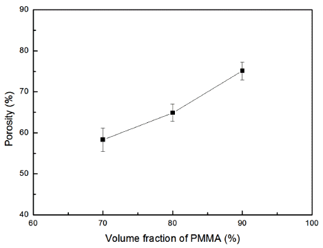
- The relative density of porous MgO preforms prepared by adding the PMMA at a ratio of 70%, 80%, and 90% was measured. Figure 3 shows the microstructure of the specimens having different volumetric ratios of the poreforming agent. The boundary between the MgO powder and the pores could be easily defined in the polished plane images. The grain size of 90 vol% of PMMA seemed to be smaller than other compositions due to its lowest green density. Figure 4 shows the relationship between the porosity and the volume fraction of PMMA for the three compositions. A linear correlation was found although the specimens were in independent experimental groups.
- The discharge performance of the porous MgO preforms having different porosities was tested, as shown in Figure 5. Three specimens for each porosity value were tested in the discharge test to verify the reproducibility. The result showed that reproducibility was considerably high, although a slight difference was found between the specimens. As shown in Figure 5, the discharge performance of all the three specimens was similar to that of the pellet-shaped electrolyte prepared by conventional pressure molding where the time required to reach the cut-off of 1.3V was typically 100 to 105 seconds. Figure 6 shows the microstructure of the cross section of the fractured separator after discharge test. Interestingly, all the molten salts included in the separator disappeared, and a number of pore channels were formed in the separator. A small amount of molten salt was found at the boundary with the electrode, indicating that the molten salt melted at high temperature during the thermal battery test was drawn into the electrode side. The amount of molten salts kept in the pore channels in the separator would be related to the size of the pore channels which is inversely proportional to the capillary force. If the size of the pore existing in the electrode is smaller than that of the pore existing in the separator, the liquid-state salts are transported to the electrode side from the separator by the difference of the capillary force.
Results and Discussion
Fig. 1
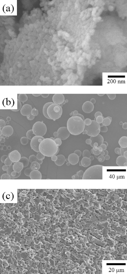
SEM micrographs of (a) MgO powder, (b) PAHM powder and (c) the sintered MgO preform with an addition of PAHM powder.

Fig. 2
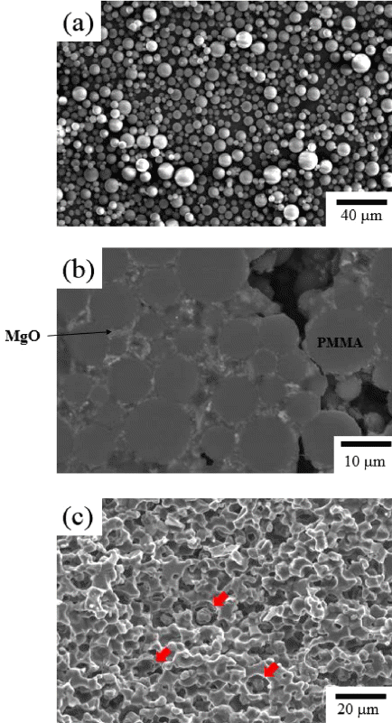
(a) SEM micrograph of PMMA powder, and cross sectional micrographs of (b) MgO green sheet with PMMA pore former, and (c) its sintered MgO preform.

Fig. 3
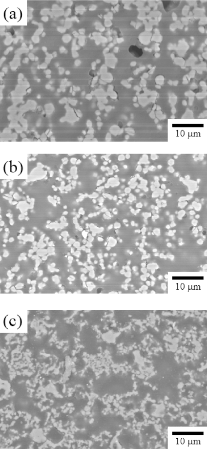
Cross sectional micrographs of Porous MgO preform (a) 70 vol% (b) 80 vol% (c) 90 vol% of PMMA.

- In the present study, to improve the powder molding method that is currently used for the electrolyte preparation process from the perspective of thermal battery stability and performance, porous MgO preforms were prepared by tape casting, molten salts were infiltrated into the preforms to prepare a new type of electrolyte separator, and the characteristics of the prepared thermal battery were evaluated. Spherical polymers were added as pore-forming agents in MgO powder, and an organic binder was used to prepare a slurry appropriate for tape casting. Several hundred micrometers of green sheets were prepared using the slurry, and 300 μm thick porous MgO preforms were prepared through binder burnout and sintering processes. PMMA with filled insides had a greater effect as a pore-forming agent in comparison with PAHM composed of hollow particles. The PMMA particles maintained their shape against the pressure applied in the forming process, while the PAHM particles were unable to do so. The porosity of the MgO preforms was controlled from 60% to 75% using a PMMA pore-forming agent. The batteries prepared using various porosities of preforms showed performance equal to or higher than that of the pellet-shaped battery prepared by the conventional powder molding method. Conclusively, the new thermal battery prepared in the present study showed better stability and performance than the conventional thermal battery.
Conclusion
-
Acknowledgements
- This study was funded by the Agency for the Defense Development of Korea. The authors wish to thank Vitzrocell Co., Ltd. for contributing to the discharge test.
Acknowledgments
- 1. R.A. Guidotti and P. Masset: J. Power Sources., (2006) 161 1443.Article
- 2. P. Masset and R.A. Guidotti: J. Power Sources., (2007) 164 397.Article
- 3. R.A. Guidotti and P.J. Masset: J. Power Sources., (2008) 183 388.Article
- 4. P.J. Masset and R.A. Guidotti: J. Power Sources., (2008) 177 595.Article
- 5. P.J. Masset and R.A. Guidotti: J. Power Sources., (2008) 178 456.Article
- 6. P. Butler, C. Wagner, R. Guidotti and I. Francis: J. Power Sources., (2004) 136 240.Article
- 7. H.W. Cheong, S.H. Ha and Y.S. Choi: Ceram. Process.., (2012) 13 308.
- 8. Y. Choi, H. Yu, H. Cheong and Y. Lee: Appl. Chem. Eng.., (2014) 25 161.Article
- 9. D.H. Doughty, P.C. Butler, R.G. Jungst and E.P. Roth: J. Power Sources., (2002) 110 357.Article
- 10. S. Martin, K. Sridharan, T. Allen, M. Mohammadian and J. Sager, Int. Pyroprocess. Res. Conf. Fontana, WI. (2012.
- 11. V. Tomeckova, J.W. Halloran and L. Gauckler: J. Am. Ceram. Soc.., (2012) 95 3763.Article
- 12. L. Yuan, Ph. D. Investigation of anode materials for lithium-ion batteries. (2006) University of Wollongong, Australia.
- 13. W. Kim, S. Lee, R. Song and J. Lee: Trans. Korean hydrogen Renewable energy Soc., (2013) 24 467.Article
- 14. F. Zhang, N. LaBarqe, W. Yang, J. Liu and B. Logan: ChemSusChem., (2015) 8 1043.Article
- 15. K.Y. Cho, D. Riu, S. Huh, D. Shin, H. Kim, J. Choi and H. Cheong: J. Korean Ceram. Soc.., (2008) 45 423.Article
- 16. R. A. Guidotti, F. W. Reinhardt and E.V. Thomas, USA, SAND99-29070. (2000.
- 17. R. A. Guidotti, F. W. Reinhardt and A. H. Andazola, SAND2002-1458. (2002.
- 18. R. Hashaikeh and J.A. Szpunar: J. Phys.., (2009) 165 012008.Article
- 19. E. L. Corral, A. Ayala, R. Loehman, R. Shah, M. Reiterer and D. Bencoe, SAND2008-0528. (2008.
- 20. K. Prasanna and C.W. Lee: J. Solid State Electrochem.., (2013) 17 1377.ArticlePDF
- 21. D. Djian, F. Alloin, S. Martinet, H. Lignier and J. Sanchez: J. Power Sources., (2007) 172 416.Article
- 22. T.H. Cho, M. Tanaka, H. Onishi, Y. Kondo, T. Nakamura, H. Yamazaki, S. Tanase and T. Sakai: J. Power Sources., (2008) 181 155.Article
- 23. S. Mei, J. Yang, X. Xu, S. Quaresma, S. Agathopoulos and J. Ferreir: J. Eur. Ceram. Soc.., (2006) 26 67.Article
- 24. L. A. Mondy, C. Roberts, A. Grillet, M. Soehnel, D. Barringer, C. Diantonio, T. Chavez, D. Ingersoll, L. Hughes, L. Evans and S. Fitchett, SAND2013-9787. (2013.
- 25. Y. Yang, J. Loomis, H. Ghasemi and G. Chen: Nano Lett.., (2014) 14 6578.Article
- 26. S.S. Zhang: J. Power Sources., (2007) 164 351.Article
- 27. X.M. Feng, X.P. Ai and H.X. Yang: Electrochem. Commun.., (2004) 6 1021.Article
- 28. S.I. Oh: Bull. Korean Chem. Soc.., (2010) 31 3723.Article
- 29. L.G. Ferguson and F. Dogan: J. Mater. Sci.., (2001) 36 137.Article
- 30. R.A. Guidotti and S. Preston: AIAA Pap.., (2007) 4.
Figure & Data
References
Citations
Citations to this article as recorded by 

Fabrication and Characterization of Thermal Battery using Porous MgO Separator Infiltrated with Li based Molten Salts


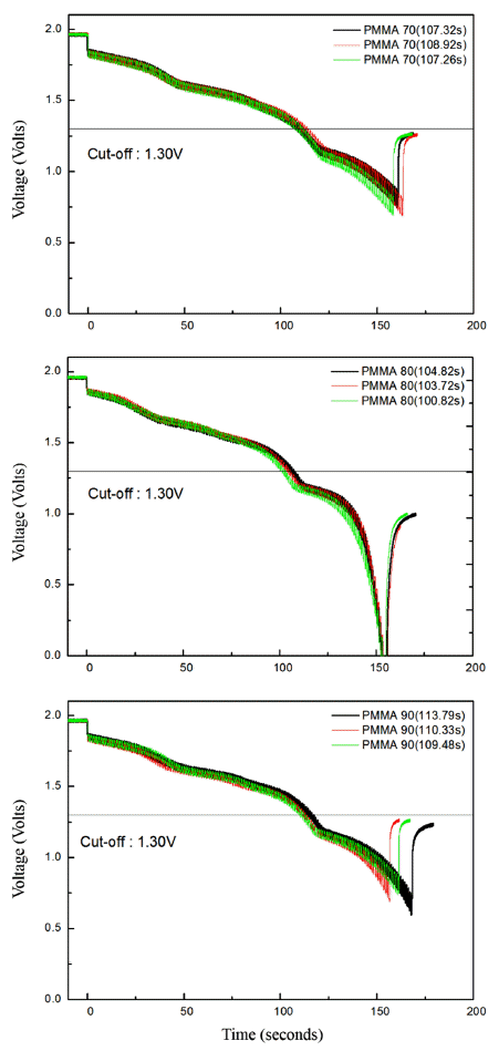
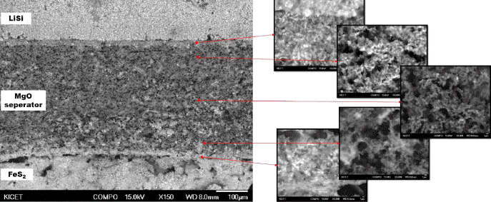
Fig. 1
SEM micrographs of (a) MgO powder, (b) PAHM powder and (c) the sintered MgO preform with an addition of PAHM powder.
Fig. 2
(a) SEM micrograph of PMMA powder, and cross sectional micrographs of (b) MgO green sheet with PMMA pore former, and (c) its sintered MgO preform.
Fig. 3
Cross sectional micrographs of Porous MgO preform (a) 70 vol% (b) 80 vol% (c) 90 vol% of PMMA.
Fig. 4
Relationship between porosity and volume fraction of PMMA for sintered MgO preform.
Fig. 5
The output voltage versus ac current curve. (a) 70 vol%, (b) 80 vol%, and (c) 90 vol% of PMMA.
Fig. 6
Cross sectional micrographs of fracture specimen after the high temperature battery test.
Fig. 1
Fig. 2
Fig. 3
Fig. 4
Fig. 5
Fig. 6
Fabrication and Characterization of Thermal Battery using Porous MgO Separator Infiltrated with Li based Molten Salts
| MgO | PMMA | solvent | binder (PVB) | plasticizer (DOP) | dispersant |
|---|---|---|---|---|---|
|
|
|||||
| 6.36 | 18.86 | 19.32 | 52.12 | 3.05 | 0.30 |
Table 1
Composition of the suspension for tape casting (wt.%)
Table 1
TOP
 KPMI
KPMI



 Cite this Article


