
Articles
- Page Path
- HOME > J Korean Powder Metall Inst > Volume 24(2); 2017 > Article
-
ARTICLE
- Lithium-silicate coating on Lithium Nickel Manganese Oxide (LiNi0.7Mn0.3O2) with a Layered Structure
- Dong-jin Kim, Da-ye Yoona, Woo-byoung Kima, Jae-won Leea,*
-
Journal of Korean Powder Metallurgy Institute 2017;24(2):87-95.
DOI: https://doi.org/10.4150/KPMI.2017.24.2.87
Published online: March 31, 2017
Department of Materials Science Engineering, Dankook University, Cheonan 31116, Republic of Korea
a Department of Energy Engineering, Dankook University, Cheonan 31116, Republic of Korea
- *Corresponding author : Jae-won Lee, +82-41-550-3682, +82-41-559-7914, jwlee7@dankook.ac.kr
• Received: March 29, 2017 • Revised: April 17, 2017 • Accepted: April 18, 2017
© The Korean Powder Metallurgy Institute. All rights reserved.
- 1,924 Views
- 7 Download
- 1 Crossref
Abstract
- Lithium silicate, a lithium-ion conducting ceramic, is coated on a layer-structured lithium nickel manganese oxide (LiNi0.7Mn0.3O2). Residual lithium compounds (Li2CO3 and LiOH) on the surface of the cathode material and SiO2 derived from tetraethylorthosilicate are used as lithium and silicon sources, respectively. Powder X-ray diffraction and scanning electron microscopy with energy-dispersive spectroscopy analyses show that lithium silicate is coated uniformly on the cathode particles. Charge and discharge tests of the samples show that the coating can enhance the rate capability and cycle life performance. The improvements are attributed to the reduced interfacial resistance originating from suppression of solid-electrolyte interface (SEI) formation and dissolution of Ni and Mn due to the coating. An X-ray photoelectron spectroscopy study of the cycled electrodes shows that nickel oxide and manganese oxide particles are formed on the surface of the electrode and that greater decomposition of the electrolyte occurs for the bare sample, which confirms the assumption that SEI formation and Ni and Mn dissolution can be reduced using the coating process.
- Lithium-ion batteries are the leading power sources for portable electronic devices and are being considered for use in electric vehicles, hybrid electric vehicles, and other energy storage systems. However, the amount of cost reduction possible for conventional cathode materials is limited because of the need to use high cost elements such as cobalt. Therefore, many studies have been conducted to develop low-cost cathode materials which contain only nickel and manganese and retain the cell performance of LiCoO2 [1-3]. However, Li(Ni,Mn)O2 has many disadvantages such as poor structure stability, poor cycling stability, and rate capability compared to the conventional cathode materials containing cobalt.
- Recently, several studies have been carried out to overcome such limitations [4-15]. Metal-oxides or phosphates coated on the cathode materials is one of the most widely used technologies to achieve high cycle stability, rate capability, and thermal stability. The formation of a metal oxides (Al2O3 or ZrO2) and metal phosphates (AlPO4) coating layer has been attempted in order to protect the cathode materials from the dissolution of the transition metal into the liquid electrolyte and also to stabilize the layer-structure of the cathode materials [4-11]. Surface modification with an electronic conductive material such as carbon was shown to be effective in enhancing the electrochemical performance of LiFePO4 [16]. Lithium-containing material (Li3PO4) with lithium-ion conductivity has been also adopted as a coating material for Li[NixMnyCo1-x-y]O2 [14]. In addition, lithium-silicate (Li4SiO4) has been coated on LiFePO4 to improve cycling stability and reduce the interfacial resistance [15].
- In this study, we applied a lithium-silicate (Li4SiO4) coating on LiNi0.7Mn0.3O2 to improve its electrochemical performance. The cell properties of LiNi0.7Mn0.3O2 as a cathode material – capacity, rate capability, and cycling stability – were measured to investigate the effect of lith- ium-silicate coating. An XPS study and a galvanostatic intermittent titration technique (GITT) measurement were also carried out to understand the reasons for the change in performances caused by the coating.
Introduction
- The lithium-silicate (LSO) coating was carried out on LiNi0.7Mn0.3O2 supplied by POSCO ES Material. Our coating process uses the residual lithium-compounds on the surface of the LiNi0.7Mn0.3O2 particle as a reactant. The content of the residual lithium-compounds was approximately 7000 ppm. The residual lithium-compounds are composed of lithium hydroxide and lithium carbonate in the molar ratio of 3:7. The other reactant for preparing LSO (SiO2) was formed on the surface of the LiNi0.7Mn0.3O2 using tetra ethyl orthosilicate (TEOS). The amount of TEOS was controlled to set the molar ratio of Si:Li (in the residual lithium-compounds) = 1:4. The lithium silicate coating content corresponds to 0.6 wt% of the LiNi0.7Mn0.3O2.
- In order to prepare a coating solution, TEOS was dropped in anhydrous ethanol and vigorously stirred. After stirring for 1 h, the coating solution was moved into the flask of an evaporator. Subsequently, the cathode material was placed into the coating solution in the evaporator. The cathode material was uniformly dispersed in the coating solution by rotating the flask of the evaporator. The evaporator was connected to an aspirator and the temperature was adjusted to 80°C to facilitate the evaporation of ethanol. The dried powder was calcined at 600°C for 4 h to facilitate a chemical reaction between the residual lithium compounds and SiO2 to generate lithium silicate on the surface of the LiNi0.7Mn0.3O2 particles.
- X-ray diffraction (XRD) analyses were carried out using an X-ray diffractometer (Rigaku, ULTIMA VI) over the 2θ range of 10° to 80° with monochromatized Cu-Kα radiation. The morphology of the powder was observed using high resolution scanning electron microscopy with an energy dispersive spectrometer (HR-SEM/ EDS, TESCAN-MIRA LMH).
- The chemical state of the surface of the electrode was analyzed using X-ray photoelectron spectroscopy (XPS, SPECS-PHOIBOS HSA3500) with a monochromatic Al Kα radiation source (1486.74 eV) operated at 400W (14.5 kV). Photoelectrons were collected in the surfacenormal direction. The electrodes were recovered from the coin-type cell after cycling, washed with di-methyl carbonate (DMC) to remove the salt (LiPF6), and dried at 40°C in a convection oven for XPS analysis.
- In order to measure the electrochemical performances, 2016 coin-type half-cells were assembled in a glovebox in which the moisture content is below 1 ppm. Lithium metal was used as a counter electrode. The cathode was fabricated by casting a slurry with a formulation of 90 wt% active material, 5 wt% acetylene black, and 5 wt% polyvinylidene difluoride(PVdF) binder on an aluminum foil. The electrolyte was 1.0M LiPF6 solution in 3:7 (vol%) ethylene carbonate (EC) : diethyl carbonate (DEC). The coin-type cells were subjected to galvanostatic cycling and galvanostatic intermittent titration technique (GITT) measurement using a cycler (PNE Solution) in the voltage range of 3.0 to 4.3 V. The specific capacity was measured at 0.1 C-rate and a rate capability test was conducted at various current densities (0.1, 0.5, 1.0, 3.0, and 7.0 C-rate). The cells were cycled for 100 cycles, charging and discharging at 1.0 C-rate, to examine the cycling stability.
Materials and methods
- Lithium silicate coating layer is supposed to be formed on the surface of the LiNi0.7Mn0.3O2 from the following reaction between the residual lithium compounds and SiO2 from TEOS.
-
- A comparison of the X-ray diffraction patterns between the bare and coated cathode materials is shown in Fig. 1. The crystal lattice constants are calculated as a=0.2886 nm, c=1.4274 nm for the bare sample and a=0.2886 nm, c=1.4265 nm for LSO coated sample. The LSO coated sample shows negligible change in the peak position and no additive peaks representing impurities generated from the coating process. The coating process is believed to cause no change of crystal structure such as doping of Si into the bare material.
- SEM and EDS analysis were conducted to examine the morphology of the samples and distribution of the coating material (Fig. 2). The particles of the bare sample exhibit the size of approximately 10 μm and a spherical shape. The particle size and shape of the LSO-coated sample are similar to those of the bare sample. The Simapping result for the LSO-coated sample indicates that the coating material is dispersed uniformly on the surface of the cathode material.
- The LSO-coated sample was subjected to XPS analysis for identifying the coating layer and the Si 2p spectrum is shown in Fig. 3. The peak can be deconvoluted to two peaks – Si 2p for SiO2 and lithium silicate, which means that the coating layer consists of lithium silicate and silica remained on the surface as shown in Fig. 4.
- Figure 5 shows the charge and discharge profiles for the 1st and 2nd cycle of the cells with the bare and LSOcoated sample at 0.1 C-rate. The reversible discharge capacities of the bare and LSO-coated sample are 156 and 154 mAh/g, respectively. The discharge capacity is not significantly reduced by the coating process. The discharge capacity of the bare sample is much lower than the layered cathode materials with cobalt and equivalent nickel content considering the discharge capacities of most nickel-rich cathode materials are greater than 180 mAh/g. However, it is generally known that cobalt plays an important role in improving the performances of the cathode materials. Li et al. has reported that LiNi0.5 Mn0.5-xCoxO2 shows a discharge capacity of 134 mAh/g with an initial efficiency of 72.4% for x=0 and the capacity and efficiency increase with the cobalt content (x) [17].
- The cycle-life performances of the bare and LSOcoated sample operated between 3.0 and 4.3 V at 0.5 Crate (charge) and 1 C (discharge) are shown in Fig. 6. The discharge capacity of the bare sample decreases gradually with cycling and finally reaches 74.2% of the initial discharge capacity after 100 cycles, while the capacity retention rate of the LSO-coated sample is improved to 82.9%. In general, the coating of the cathode material enhances the cycling stability and the reason is believed to be the reduction of contact between the electrode and electrolyte leading to suppression of their reaction. Consequently, the formation of the solid electrolyte interface (SEI), which is a product of the reaction, can be reduced using a coating process. A more detail discussion is given in the results of XPS analysis.
- Rate capability is an important requirement for battery performance because the charging time of batteries in portable electric devices depends on the rate of Li+ extraction and intercalation. The rate capabilities of the bare and LSO-coated sample were measured at various discharge current densities (0.5, 1, 3, 5, and 7 C-rate) and a fixed charge current density (0.5 C-rate). When the discharge current density is increased to 7C, the discharge capacity of the bare sample retains only 62.7% of that at 0.5 C-rate while the LSO-coated sample shows 71.3% of capacity retention (Fig. 7). From the above result, Li-ion conducting ceramics coating is expected to enhance the rate capability. The reason for the improvement may be the decrease of the interfacial resistance of the electrode. The amount of the residual lithium compounds was reduced to ~3000 ppm after the lithium silicate coating and they were converted to lithium silicate which is more beneficial to lithium-ion conducting. This is believed to be crucial for the improvement of rate capability.
- In order to find the origin of the better rate performance of the LSO-coated sample, the chemical diffusion coefficient of Li+ (
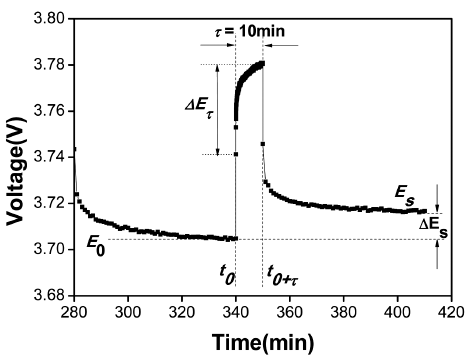
- The applied current flux and the resulting voltage profile for a single titration at 3.7 V are shown in Fig. 9 with a schematic labeling of the relevant parameters. On the application of a constant current (I0 = ~ 400 μA; C/5rate) at time t = t0 for a duration of τ = 10 min, the cell voltage (E) increases from its equilibrium value (E0) with time, which is super-imposed to an IR drop due to the current flux through the electrolyte and interface. The total change in cell voltage ΔEτ during the current flux was obtained by subtracting the IR drop as shown in Fig. 9. The current was interrupted after a time τ (t = t0 + τ) and the cell was kept under OCV for 1 h to relax into the new steady-state potential Es, from which the change in the steady-state voltage ΔES (= Es – E0) over the galvanostatic titration was determined. After a series of assumptions and simplifications, for a sufficiently small current, where ΔES for a single titration is small, the equation for DLi can be written as
- where VM is the molar volume of the electrode active material. MB and mB are its molecular weight and mass, respectively, and S the total contact area between the electrolyte and the electrode. In our calculations, we assumed that VM remained a constant without changing the Li-content in the cathode. The active surface area of the electrode is the specific surface area of the electrode material (~0.38 m2/g) determined using the BET method. This is a suitable choice assuming that the electrode could entirely absorb the electrolyte.
- Figure 10 shows
- After the 100 cycles, all the electrodes were examined in the discharged state by XPS to compare the differences. The C 1s, O 1s, F 1s, Mn 2p, and Ni 2p multiplex spectra for the cycled electrodes are provided in Figures 11 to 15 and the atomic % of each element is listed in Table 1. Quinlan et al. carried out an XPS study extensively on LiNi0.5Mn0.5O2 and we used the binding energies identified in their study [20].
- C 1s region – The surface chemistry of our LiNi0.7Mn0.3 O2 electrodes is very similar to that studied by Quinlan et al. [20]. The binding energies were confirmed with the sub-peaks at 284.4 (carbon black), 285.3 (PVdF), 288.3 (C=O, degradation products of the electrolyte), 286.5 (C-O, degradation products of the electrolyte), and 290.7 eV (PVdF). The carbon black contribution (284.4 eV) decreases slightly upon cycling. The LSO-coated electrode shows lower intensity of the sub-peaks at 288.3 eV (C=O) and 286.5 eV (C-O) than the bare electrode after cycling. From the above results, it is assumed that LSO-coating suppresses the side reactions between the electrode and electrolyte and the formation of the surface film.
- O 1s region – The peak locations for lattice oxygen in LiNi0.7Mn0.3O2 (529.2 eV), surface oxygen in LiNi0.7Mn0.3O2 (531.1 eV), C-O (532.6 eV), and LiPF6 degradation products (LixPFyOz) (533.9 eV) are denoted by dashed vertical lines in the figure. The higher intensity at 533.9 eV (LixPFyOz) for the cycled bare electrode indicates that more LiPF6 is degraded and deposited to form a film layer on the surface of the electrode during the cycling. From the result, LSO coating seems to prevent the formation of the SEI layer, suppressing the side reaction between the electrode and electrolyte. For the bare electrode, there is little change in the contribution of the lattice oxygen before and after the cycling, while the peak intensity of the lattice oxygen is decreased for the LSO-coated electrode after the cycling. It has been reported that high concentration of the lattice oxygen of the bare electrode represents the formation of metal oxides in a form other than LiNi0.7Mn0.3O2 on the surface [21]. The metal oxides are the product of the oxidation of the metal (nickel and manganese) ions dissolved from the cathode material into the electrolyte. The higher atomic % of oxygen in the bare electrode after the cycling, as listed in Table 1, may be an evidence for the metal oxides formation. The thicker LixPFyOz film and metal oxide particles of the bare electrode is believed to increase the interfacial resistance and the gradual dissolution of the transition metal into the electrolyte leads to poor cycling stability.
- F 1s region – The F 1s core peaks are shown in Fig. 13. The binding energies for LixPFyOz (686.6 eV) and PVdF (687.6 eV) are identified by dashed vertical lines. For the cycled electrodes, the sub-peak at 686.6 eV is assigned to the LiPF6 degradation products (LixPFyOz). The LSOcoated electrode shows a lower contribution at 686.6 eV than the bare electrode. This result is in agreement with the spectra in the O 1s region.
- Mn 2p region – The 2p3/2 and 2p1/2 regions were used to indicate the chemical state of Mn in the electrodes. The dashed vertical lines denote 2p1/2 and 2p3/2 of LNMO, the F KLL Auger. The intensities of the peaks for Mn 2p1/2 and 2p3/2 of LNMO do not change significantly after the cycling for the bare electrode, in spite of the masking effect due to the surface film, which implies the formation of manganese oxides on the surface of the cathode during the cycling. Compared with the bare electrode, the LSO-coated electrode shows lower intensities for those signals after the cycling (0.5 and 1.2 atomic % of Mn in the LSO-coated electrode and the bare electrode, respectively), which indicates less formation of the manganese oxides. The LSO-coated electrode displays two spin-orbit peaks (2p1/2 and 2p3/2) of MnF2 binding energies at 656.4 eV and 643.8 eV, respectively while these peaks are not detected in the cycled bare electrode. LSO-coating is believed to suppress the formation of manganese oxide and promote the MnF2 formation, which may contribute to the better cycling stability of the LSO-coated electrode.
- Ni 2p region – The Ni 2p3/2 regions are shown in Fig. 15. The binding energies for NiF2 (859.23 eV), Ni3+ 2p3/2 of LiNi0.7Mn0.3O2 (856.56 eV), and Ni2+ 2p3/2 of LiNi0.7Mn0.3O2 (855.06 eV) are identified by dashed vertical lines. The metal fluorides do not appear in the F1s spectra due to the high signal of LixPFyOz. The cycled bare and LSO-coated electrodes exhibit increased concentration for NiF2 than before cycling. In contrast, the signal of Ni2+ 2p3/2 disappears after cycling for the LSO-coating electrode. The lowered signal of Ni2+ 2p3/2 for the cycled LSO-coated electrode represents the formation of the surface film after cycling. However, for the cycled bare electrode, the signal of Ni2+ 2p3/2 as well as Ni3+ 2p3/2 is observed. The signals represent the formation of the metal oxides on the surface of the electrode due to the dissolution of the transition metal in LiNi0.7Mn0.3O2. In addition, the LSOcoated electrode shows lower intensities than the bare electrode for Ni after the cycling as listed in Table 1 (4.6 and 5.9 atomic % of Ni 2p in the LSO-coated electrode and the bare electrode, respectively), which indicates much less formation of the nickel oxides. From the above observations, the bare electrode is believed to have comparable amounts of NiF2 and more amounts of nickel oxides (NiO and Ni2O3) on the surface than the LSOcoated electrode after cycling.
- The XPS analysis results show that the surface chemistry of the bare and LSO-coated samples after cycling is somewhat different and it is displayed in Fig. 16. We can summarize the results, whereby the thickness of the film formed from the decomposition of the electrolyte components (EC, DEC, and LiPF6) is decreased and the metal fluorides, especially MnF2, are promoted by coating with LSO. The formation of transition metal fluorides has been observed on the surface of the LiNi0.5Mn0.5O2 electrodes during cycling in LiPF6/EC-DEC solution and is believed to protect the electrode effectively [22].
- Consequently, coating with LSO appears to suppress the dissolution of the transition metal from LiNi0.7Mn0.3O2 and oxidation of the dissolved metal ions, which is the main reason for the better cycling stability of the LSO-coated electrode.
Results and discussion
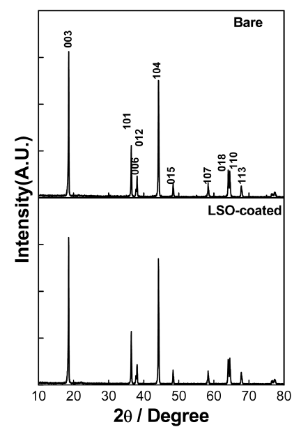
Fig. 2
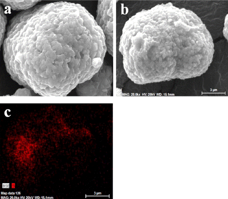
Morphologies and distribution of the coating material (LSO) on the surface of LiNi0.7Mn0.3O2 SEM images of (a) the bare and (b) LSO-coated sample. (c) EDS image of Simapping of the LSO-coated sample.
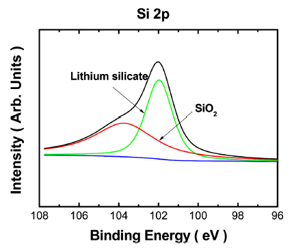
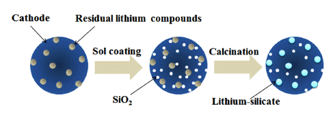
Fig. 5
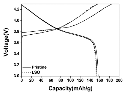
The 1st and 2nd charge/discharge profiles of the bare and LSO-coated LiNi0.7 Mn0.3O2 in the voltage range of 3.0 to 4.3 V at 0.1C.
Fig. 6
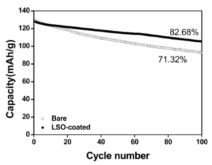
Cycle-life performance of the bare and LSO-coated LiNi0.7Mn0.3O2. (Cycled at 0.5C-charge/1C-discharge)
Fig. 7
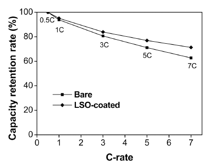
Rate capability of the samples. Capacity retention rate of the bare and LSO-coated LiNi0.7Mn0.3O2 cathode in the voltage range of 3.0 to 4.3 V at different current densities.
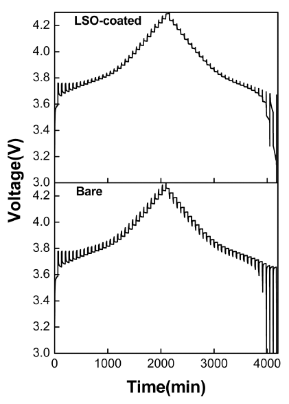
Fig. 9

Schematic representation of a single step of the GITT. Applied current pulse vs. voltage profile for a single titration at 3.7 V during the 5th charge pulse for the bare electrode/Li half-cell.
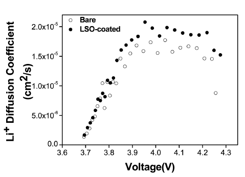
Fig. 11
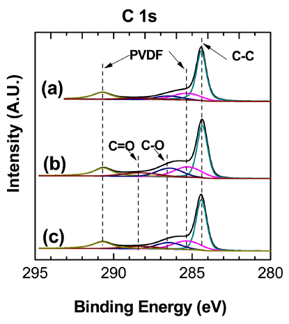
XPS spectra of the C 1s photoemission region of (a) the bare electrode before cycling, (b) the bare electrode after cycling, and (c) the LSO-coated electrode after cycling.
Fig. 12
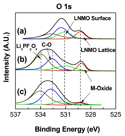
XPS spectra of the O 1s photoemission region of (a) the bare electrode before cycling, (b) the bare electrode after cycling, and (c) the LSO-coated electrode after cycling.
Fig. 13
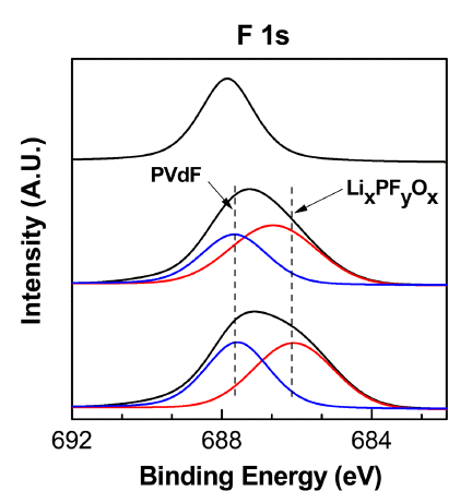
XPS spectra of the F 1s photoemission region of (a) the bare electrode before cycling, (b) the bare electrode after cycling, and (c) the LSO-coated electrode after cycling.
Fig. 14
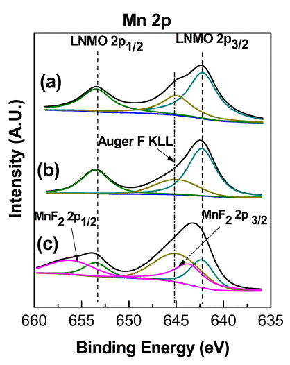
XPS spectra of the Mn 2p photoemission region of (a) the bare electrode before cycling, (b) the bare electrode after cycling, and (c) the LSO-coated electrode after cycling.
Fig. 15
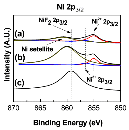
XPS spectra of the Ni 2p photoemission region of (a) the bare electrode before cycling, (b) the bare electrode after cycling, and (c) the LSO-coated electrode after cycling.
Table 1
Atomic % of each element estimated by XPS analysis
| Atomic % | F (%) | C (%) | O (%) | Mn (%) | Ni (%) | Total (%) |
|---|---|---|---|---|---|---|
|
|
||||||
| Bare | 32.3 | 54.9 | 7.7 | 0.5 | 4.6 | 100 |
| LSO-coated | 27.7 | 55.2 | 10.0 | 1.2 | 5.9 | 100 |
Fig. 16
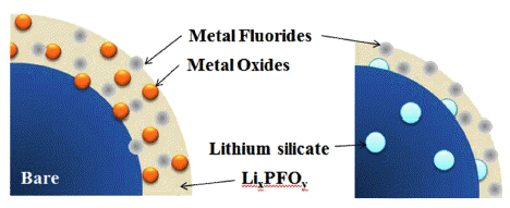
Schematic diagram of the surface chemistry of the bare and LSO-coated electrode after cycling.
- The lithium-silicate coating was applied on a layerstructured cobalt free cathode material (LiNi0.7Mn0.3O2) to improve the rate capability and cycle life performance. We used residual lithium-compounds as a lithium source for lithium-silicate to minimize the effect of Li2CO3 and LiOH on the surface of the cathode material and to enhance the rate and cycling performance. Moreover, the coating is expected to facilitate the mobility of lithium-ion at the interface of the electrode and electrolyte as lithium-silicate is one of the lithium-ion conducting materials. XRD and SEM/EDS analysis were used to confirm that no change occurred in the crystalline phase and uniform dispersion of the coating material, respectively. Although the chemical diffusion coefficient of lith- ium-ion is not increased greatly by the coating, the interfacial resistance appears to be decreased significantly considering the better rate capability and cycling stability of the coated sample. The reason for the lowered interfacial resistance was studied using XPS analysis. Metal (Ni-, Mn-) oxide originating from the dissolution of the transition metal was not observed and less decomposition product of the electrolyte was deposited during cycling for the LSO-coated sample; the latter is believed to be the main reason for the better cell performance achieved by the coating.
Conclusions
- 1. M.E. Spahr, P. Novak, B. Schnyder, O. Haas and R. Nesper: J. Electrochem. Soc., (1998) 145 1113.ArticlePDF
- 2. S. Gopukumar, K.Y. Chung and K.B. Kim: Electrochim. Acta., (2004) 49 803.Article
- 3. G.M. Koenig, I. Belharouak, H. Deng, Y.K. Sun and K. Amine: Chem. Mater., (2011) 23 1954.Article
- 4. J. Cho, T.G. Kim, C. Kim, J.G. Lee, Y.W. Kim and B. Park: J. Power Sources., (2005) 146 58.Article
- 5. S.T. Myung, K. Izumi, S. Komaba, Y.K. Sun, H. Yashiro and N. Kumagai: Chem. Mater., (2005) 17 3695.Article
- 6. Y. Kim, H.S. Kim and S.W. Martin: Electrochim. Acta., (2006) 52 1316.Article
- 7. Q. Qiu, X. Huang, Y. Chen, Y. Tan and W. Lv: Ceram. Int., (2014) 40 10511.Article
- 8. J. Cho, T.J. Kim, Y.J. Kim and B. Park: Electochem. Solid-State Lett., (2001) 4 A159.Article
- 9. S.M. Lee, S.H. Oh, J.P. Ahn, W.I. Cho and H. Jang: J. Power Sources., (2006) 159 1334.Article
- 10. Y. Huang, J. Chen, J. Ni, H. Zhou and X. Zhang: J. Power Sources., (2009) 188 538.Article
- 11. S.K. Hu, G.H. Cheng, M.Y. Cheng, B.J. Hwang and R. Santhanam: J. Power Sources., (2009) 188 564.Article
- 12. Z. Zhang, Z. Gong and Y. Yang: J. Phys. Chem., (2004) 108 17546.Article
- 13. T. Liu, S.X. Zhao, K. Wang and C.W. Nan: Electrochim. Acta., (2012) 85 605.Article
- 14. H.G. Song, J.Y. Kim, K.T. Kim and Y. Park: J. Power Sources., (2011) 196 6847.Article
- 15. Q. Zhang, W. Jiang, Z. Zhou, S. Wang, X. Guo, S. Zhao and G. Ma: Solid State Ion., (2012) 218 31.Article
- 16. H. Huang, S.C. Yin and L.F. Nazar: Electrochem. Solid-State Lett., (2001) 4 A170.Article
- 17. D. Li, Y. Sasaki, M. Kageyama, K. Kobayakawa and Y. Sato: J. Power Sources., (2005) 148 85.Article
- 18. K.M. Shaju, G.V. Rao and B.V. Chowdari: Electrochim. Acta., (2003) 48 2691.Article
- 19. Z. Li, F. Du, X. Bie, D. Zhang, Y. Cai, X. Cui, C. Wang, G. Chen and Y. Wei: J. Phys. Chem. C., (2010) 114 22751.Article
- 20. R.A. Quinlan, Y.C. Lu, S.H. Yang and A.N. Mansour: J. Electrochem. Soc., (2013) 160 A669.Article
- 21. L. Baggetto, N.J. Dudney and G.M. Veith: Electrochim. Acta., (2013) 90 135.Article
- 22. B. Markovsky, D. Kovacheva, Y. Talyosef, M. Gorova, J. Grinblat and D. Aurbach: Electrochem. Solid-State Lett., (2006) 9 A449.Article
References
Figure & Data
References
Citations
Citations to this article as recorded by 
- Artificial cathode-electrolyte interphases on nickel-rich cathode materials modified by silyl functional group
Hye Ji Song, Seol Heui Jang, Juhyeon Ahn, Si Hyoung Oh, Taeeun Yim
Journal of Power Sources.2019; 416: 1. CrossRef
 Cite this Article


Lithium-silicate coating on Lithium Nickel Manganese Oxide (LiNi0.7Mn0.3O2) with a Layered Structure


Fig. 1
X-ray diffraction patterns of the bare and LSOcoated LiNi0.7Mn0.3O2.
Fig. 2
Morphologies and distribution of the coating material (LSO) on the surface of LiNi0.7Mn0.3O2 SEM images of (a) the bare and (b) LSO-coated sample. (c) EDS image of Simapping of the LSO-coated sample.
Fig. 3
Si 2p XPS spectrum for the LSO-coated sample.
Fig. 4
Schematic diagram of the LSO coating process.
Fig. 5
The 1st and 2nd charge/discharge profiles of the bare and LSO-coated LiNi0.7 Mn0.3O2 in the voltage range of 3.0 to 4.3 V at 0.1C.
Fig. 6
Cycle-life performance of the bare and LSO-coated LiNi0.7Mn0.3O2. (Cycled at 0.5C-charge/1C-discharge)
Fig. 7
Rate capability of the samples. Capacity retention rate of the bare and LSO-coated LiNi0.7Mn0.3O2 cathode in the voltage range of 3.0 to 4.3 V at different current densities.
Fig. 8
GITT curves of the bare and LSO-coated LiNi0.7 Mn0.3O2 measured in the range of 3.0 to 4.3 V.
Fig. 9
Schematic representation of a single step of the GITT. Applied current pulse vs. voltage profile for a single titration at 3.7 V during the 5th charge pulse for the bare electrode/Li half-cell.
Fig. 10
Chemical diffusion coefficients of lithium-ion in the bare and LSO-coated LiNi0.7Mn0.3O2.
Fig. 11
XPS spectra of the C 1s photoemission region of (a) the bare electrode before cycling, (b) the bare electrode after cycling, and (c) the LSO-coated electrode after cycling.
Fig. 12
XPS spectra of the O 1s photoemission region of (a) the bare electrode before cycling, (b) the bare electrode after cycling, and (c) the LSO-coated electrode after cycling.
Fig. 13
XPS spectra of the F 1s photoemission region of (a) the bare electrode before cycling, (b) the bare electrode after cycling, and (c) the LSO-coated electrode after cycling.
Fig. 14
XPS spectra of the Mn 2p photoemission region of (a) the bare electrode before cycling, (b) the bare electrode after cycling, and (c) the LSO-coated electrode after cycling.
Fig. 15
XPS spectra of the Ni 2p photoemission region of (a) the bare electrode before cycling, (b) the bare electrode after cycling, and (c) the LSO-coated electrode after cycling.
Fig. 16
Schematic diagram of the surface chemistry of the bare and LSO-coated electrode after cycling.
Fig. 1
Fig. 2
Fig. 3
Fig. 4
Fig. 5
Fig. 6
Fig. 7
Fig. 8
Fig. 9
Fig. 10
Fig. 11
Fig. 12
Fig. 13
Fig. 14
Fig. 15
Fig. 16
Lithium-silicate coating on Lithium Nickel Manganese Oxide (LiNi0.7Mn0.3O2) with a Layered Structure
| Atomic % | F (%) | C (%) | O (%) | Mn (%) | Ni (%) | Total (%) |
|---|---|---|---|---|---|---|
|
|
||||||
| Bare | 32.3 | 54.9 | 7.7 | 0.5 | 4.6 | 100 |
| LSO-coated | 27.7 | 55.2 | 10.0 | 1.2 | 5.9 | 100 |
Table 1
Atomic % of each element estimated by XPS analysis
Table 1
TOP
