
Articles
- Page Path
- HOME > J Korean Powder Metall Inst > Volume 27(1); 2020 > Article
-
ARTICLE
- Spark Plasma Sintering of the Ni-graphite Composite Powder Prepared by Electrical Explosion of Wire in Liquid and Its Properties
- Minh Thuyet-Nguyenaa, Jin-Chun Kimb,*
-
Journal of Korean Powder Metallurgy Institute 2020;27(1):14-24.
DOI: https://doi.org/10.4150/KPMI.2020.27.1.14
Published online: January 31, 2020
a School of Materials Science and Engineering, Hanoi University of Science and Technology, No 1, Dai Co Viet, Hai Ba Trung, Hanoi 100000, Vietnam
b School of Materials Science and Engineering, University of Ulsan, 93 Daehak-ro, Nam-gu, Ulsan 44610, Republic of Korea
- *Corresponding Author: Jin-Chun Kim, TEL: +82-52-712-8061, FAX: +82-52-259-1688, E-mail: jckimpml@ulsan.ac.kr
- - M. Thuyet-Nguyen: 전임강사, 김진천: 교수
• Received: February 17, 2020 • Revised: February 21, 2020 • Accepted: February 21, 2020
© The Korean Powder Metallurgy Institute. All rights reserved.
- 1,462 Views
- 3 Download
- 2 Crossref
Abstract
- In this work, the electrical explosion of wire in liquid and subsequent spark plasma sintering (SPS) was introduced for the fabrication of Ni-graphite nanocomposites. The fabricated composite exhibited good enhancements in mechanical properties, such as yield strength and hardness, but reduced the ductility in comparison with that of nickel. The as-synthesized Ni-graphite (5 vol.% graphite) nanocomposite exhibited a compressive yield strength of 275 MPa (about 1.6 times of SPS-processed monolithic nickel ~170 MPa) and elongation to failure ~22%. The hardness of Nigraphite composite had a value of 135.46 HV, which is about 1.3 times higher than that of pure SPS-processed Ni (105.675 HV). In terms of processing, this work demonstrated that this processing route is a novel, simple, and low-cost method for the synthesis of nickel-graphite composites.
- Carbonaceous nanomaterials, including carbon nanotubes (CNTs), graphene and graphite nanosheet have remarkable potentials about mechanical and physical properties that could be listed as high mechanical strength, high elastic modulus as well as the high electrical and thermal conductivity material, which makes them become promising candidates for structural engineering and functional device applications [1]. Graphite recently has attracted considerable attention not only as a costeffective substitute for carbon nanotubes but also enhance the mechanical properties, corrosion resistance and lighten the weight of parts in various industrial applications [2]. Moreover, because of the excellent thermal conductivity, the graphite helps to dissipate the heat, therefore, metal-graphite composites are widely used for thermal management components in electronic devices. In addition, metal matrix-graphite composites with the magnetic matrices are promising materials due to the high potentials for applying in the magnetic field such as recording devices, magnetic shielding [3-6]. Among many kinks of metal-graphite composites, Ni-graphite composites are widely used in many applications such as conductive fillers [7], self-lubrication parts for automotive industry and tribological engineering parts [8, 9]. It was also used in electromagnetic interference (EMI) gaskets, microwave absorber application [10] because of the positive characteristics which were the combination of thier components such as the good thermal, electrical conductivity and magnetic properties of nickel and the low thermal expansion coefficient, high lubrication properties of graphite [11, 12]. Up to now, Ni-graphite composites have been mainly used in Ni-coated graphite powder type which was usually fabricated by using chemical and physical techniques such as oxidation and reduction methods [13, 14], or electroless deposition in alkaline coating bath [10, 15, 16]. Ni nanoparticles and Ni coated graphite composite were also widely used in coating or thin film types which have been applied in many applications requiring friction and wear resistance behavior [11, 17]. In term of bulk materials, the Nigraphite composites have received less attention. They were typically prepared by a powder metallurgy (PM) process [8, 9, 18, 19]. However, the PM has certain limitations that primarily related to the poor affinity between Ni and graphite materials. This was not only led to the rising of weak interfaces between them but also negative effects on the structural, mechanical and magnetic properties of their composites. In addition, the expensive price of the initial powder materials is also known as a disadvantage of the PM process. Therefore, new methods for synthesis of this composite type have still got a lot of attention from researchers and manufacturers.
- In this work, we present a new processing route which is the combination of EEW, ultrasonication and SPS methods for synthesizing the Ni-graphite nanocomposites. It is noted that the EEW process has been widely used to fabricate various types of nanosized metallic particles as well as metallic alloyed powders. In addition, the electrical conductivity of graphite enables the EEW to produce nanosized graphite powder from graphite rods. Based on that concept, in this work, Ni-graphite nanocomposite powders were firstly fabricated by the EEW, subsequently sintered by the spark plasma sintering (SPS) process to get the bulk specimens. The properties of the as-synthesized composites include phases, mechanical were investigated then.
1. Introduction
- Graphite rods with a diameter of 0.5 mm and Ni wires (purity of 99%) with a diameter of 0.25 mm were used in this work. Before exploding in EEW, the graphite rods were treated with a solution of nitric acid for 12-24 hours, then they were washed with deionized water and ethanol for several times and dried at 60 °C for 5 hours. The dried graphite rods were exploded in ethanol to produce the graphite suspension. This suspension was ultrasonicated for about 1 hour to obtain the better homogenous. Subsequently, EEW was continuously performed to explode Ni wires (0.25 mm diameter and 40 mm length) in the as-prepared graphite suspension to fabricate the Ni-graphite composite. The explosion times of the graphite rod and Ni wires were calculated based on the volume fraction of graphite and Ni in the desired composite following the formulas (1), (2) and (3). According to these formulas, the ratio x/y is obviously calculated. Thus, with each value of x that we picked up, there is a correlative value of y. Therefore, the number of the explosion was determined. In this study, the volume fraction of Ni and graphite in their composite was 95 vol.% and 5 vol.%, respectively.
- Where: Vgraphite and Vnickel are volume fraction of graphite and nickel in the desire composite; R1- radius of graphite rod; R2- is radius of Ni wire; L- the required length for using in EEW and x, y are the number of explosions of graphite rod and Ni wirein EEW, respectively.
- After the explosion the as-exploded Ni-graphite composite powders were collected from their suspension and drying at 80 °C under vacuum. Then, a heat treatment stage in H2 atmosphere condition for 2 hours at 400 °C was used to complete the synthesis of Ni-graphite composite powders. TheNi-graphitenano composite powders were then consolidated in the SPS equipment (Mod. 115S, Sumitomo Coal Mining Co.Ltd., Japan) at various temperatures (900 °C, 1000 °C and 1100 °C) in vacuum condition under a pressure of 50 MPafor 10 minutes. The heating rate of SPS process was maintained at 50 °C/min.
- A JSM-6500F field emission scanning electron microscope (FE-SEM) and the X-ray diffraction (XRD) analyses (RigakuUltima III) were employed to observe the surface morphology, phases and microstructures of both powders and bulk samples. The density of the sintered specimens was measured by the Archimedes method. The microhardness was measured by using a standard Vickers microhardness tester (Mitutoyo MVK-H1) under a load of 100 g for 15 seconds. In order to obtain a statistical distribution which reliably depicts the hardness of the sample, 10 times measurements were performed on each sample. The compression tests were carried out on cylindrical specimens according to the standard ASTM E9-89a by using an INSTRON 5582 equipment to assess the strain, stress and deformation behaviors of the as-sintered composites.
2. Experimental
- 3.1 Characterization of as-synthesized graphite and Ni-graphite composite powders
- The morphology of the as-prepared graphite in EEW was observed by FE-SEM analysis, the results are shown in Fig. 1. The FE-SEM images show that the as-prepared graphite was in form of graphite sheets with the thickness of ~30 nm demonstrating that graphite nanosheets were successfully fabricated by exploding of graphite rods in EEW with ethanol condition. In Fig. 1(a) the graphite nanosheets were stuck together because of the agglomeration phenomenon in nano materials. Therefore, to overcome this phenomenon, after EEW the graphite suspension was ultrasonicated for 1 hour and, due to the effects of ultrasonic vibration16) and as shown in the Fig. 1(b), the graphite sheets were separated and relatively uniform with the diameter under 3 μm and the thickness of ~30 nm. The as-prepared graphite nanosheets exhibited a very thin thickness that means they could be endowed with the large surface area, an excellent property which is responsible for the formation of an electrical conductor within the composite or coating materials at the low graphite contents.
- In a next step, Ni wires were exploded in the graphite suspension to produce Ni-graphite composite powders which were then collected, dried and heat treated in H2 condition. Fig. 2 shows the morphology of the dried and heat treated powders. It could be seen that the Ni particles were in spherical shapes and the particle sizes could be classified into two groups: the first one (nanoparticles) with a diameter under 100 nm and the second one (fine particles) with a diameter larger than 100 nm, however, the first group is dominant. Furthermore, the FESEM images show that the graphite sheetswere coated by Ni particles on their surfaces. It could be thought that the Ni-coated graphite composite was formed during the EEW process due to the explosion of Ni wires to form Ni nanoparticles and the expansion of Ni nanoparticles into the graphite suspension. The expansion of Ni nanoparticles was random, therefore, the coating and the distribution of Ni particles on the graphite nanoplates surface was also random. However, from SEM images we could observe that Ni particles coated tightly and homogeneously on the surface of graphite nanosheets, even after heat treatment the coating still exhibited a clearly sesame- seed structure. It was seemed smoother and stronger than that in the as-prepared powders without heat treatment (Fig. 2). Moreover, Ni is known as a good coating ability material therefore, it could play of a valuable role in the formation of Ni-coated graphite composite powders in EEW process.
- The XRD diffraction patterns of the as-prepared powders before and after heat treatment are shown in Figure 3 and Figure 4, respectively. For comparison, phase analysis of pure Ni is also given out. It can be seen that the exploded graphite nanosheets exhibited a typical graphite pattern (Fig. 3). Indeed, the two diffraction peaks at 2θ = 26.5° and 54.5° correspond to the graphite planes (002) and (004) were observed. These peaks were also observed in the diffraction profile of the Ni-graphite powders but the intensity of them were smaller than that due to the small content of the graphite in the composite and the existence of the coated Ni particles layer on the graphite sheets surfaces. The as-exploded Ni and Nigraphite powders exposed the typical diffraction peaks of Ni at 2θ = 44.5°; 51.8°; and 76.4°, which was consistent with the indices (111), (200) and (220) of the pure facecentered cubic (fcc) Ni, respectively. However, in comparing with the diffraction patterns of pure Ni, the Nigraphite composite showed some strange peaks, and most of those peaks could not be assigned. This was attributed to the effects of organic solvent (ethanol) on the structure of the products which was reported in some previous studies [20, 21]. Thus, carbon and oxygen atoms diluting in the solvent were incorporated in the Ni crystal structure led to the formation of the metastable phases during the explosion of Ni wires inthe ethanol condition. Furthermore, in order to figure out the elements incorporated in the Ni structure, in a previous study, Cho et al. [21] applied a method named extraction ion chromatography under an Ar atmosphere for investigation. They reported that the powders which were exploded in ethanol contained amounts of carbon and oxygen, the evolved gas consists of nickelocene, carbon monoxide, and carbon dioxide and during heat treatment carbon and oxygen escape from the interstitial sites of the Ni structure. The XRD patterns of heat treated powders are presented in figure 4. After treating in the hydrogen atmosphere, powders were in the pure phase of Ni and graphite. Thus, only three typical peaks of pure Ni and a small peak of graphite were observed in the XRD patterns illustrating the crystalline structure of Ni is recovered.
- 3.2. Spark plasma sintering of Ni-graphite composite powders
- The above as-synthesized Ni-graphite composite powders were then sintered by using SPS machine at 900 °C, 1000 °C and 1100 °C to obtain bulk samples. To evalu- ate the sintering process and the effect of the sintering temperatures on the characteristics of the sintered bodies, the fracture surface of the sintered specimens was examined and presented in Figure 5. The sample processed at 900 °C (Fig. 5 a, b) shows no significant signs of necking, but still looks similar to a pressed, greenbody powder, the consolidation of composite powders caused by the pressure mainly resulting in no sintering stage occurred at this temperature. At the higher temperatures, the fracture surfaces showed the difference in comparison with that at 900 °C. Thus, the fracture surfaces of sintered specimens processed at 1000 °C (Fig. 5 c and d) exhibited the bonding traces between particles corresponding to the formation of necks and the occurring of the sintering stage. Those phenomena were more evidently observed on the whole fracture surface of the sample sintered at 1100 °C (Fig. 5 e and f). Thus, the micrographs were more like a true fracture surface where the rough surfaces seem to be caused by the tearing motion used during fracture. These fracture surfaces also exposed typical cup and cone type failure characteristics, showing dimples of the order of a few microns in size. In addition, from the micrographs at a higher magnification (Fig. 5 d and f) the dark area with the size of about 1 micron which was attributed the graphite could be observed at the dimple positions on the fracture surface. From these results, it could be concluded that the mass transformation phenomena which was responsible for the formation and the growth of the necks mainly occured between 1000 °C and 1100 °C and the sintering of the Ni-graphite composite powder was better to taken place at 1100 °C.
- 3.3. Characterization of the as-sintered Ni-graphite composites.
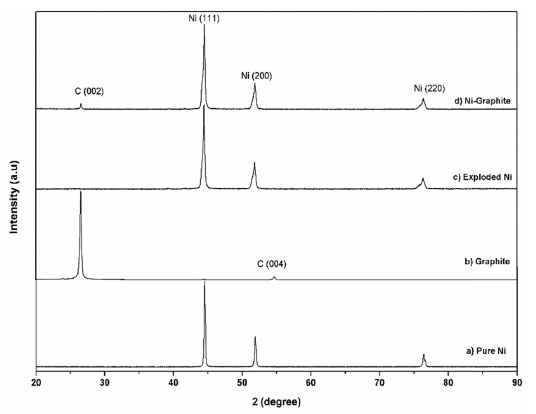
- The XRD patterns of the SPS processed Ni-graphite composites are shown in Figure 6. Only carbon and nickel phases were observed in the sintered samples which were confirmed by the typical peaks of pure Ni and a small peak of carbon. In all samples, three typical diffraction reflection peaks of Ni were observed, namely (111), (200) and (220) corresponding to crystallographic planes of nickel at 2θ = 44.5°; 51.8°; and 76.4°, respectively. No Ni carbides or oxides were detected in any of those samples, implying that no graphite degradation occurred into Ni3C or NiC. In addition, a small peak at 2θ = 26.5o was attributed to graphite, confirming the presence of graphite in sintered samples without any other interfacial product/carbide formation, thus there was no chemical reaction between Ni and graphite during the sintering process.
- The microstructure of bulk sample’s surface was observed by FE-SEM and shown in Fig. 7. It could be seen that at 900 °C was not sintered, therefore, it exhibited the rough surface after polishing. At higher sintering temperature, the bulk sample was in dense with a smoother surface. The high magnification FE-SEM images (Fig. 8) exposed the dense of sintered bodies demonstrated one more time that the samples were consolidated better with the sintering temperature of 1000 - 1100 °C (Fig. 8b) in comparison with that at 900 °C (Fig. 7a). Based on the EDS mapping data, sintered samples showed only the distribution of Ni and carbon phases corresponding to XRD results. Generally, the carbon and Ni elements distributed whole the matrix of the bulk sample quite homogeneously (Fig. 7). However, in SEM images (Fig. 8) a second very dark phase was observed on the smooth and dense surface of the matrix. It was attributed the agglomeration of graphite nanosheets which were then confirmed by EDS analysis results showing in Fig. 9. The size of the agglomeration was detected under 5 μm which is really smaller than that of 10-15 μm in some previous studies where the mechanical milling or other mixing methods were used before sintering [22-24]. This indicates the novelty of the use of EEW, ultrasonication methods in our work in term of achieving the homogeneous Ni-graphite composite powders and leading to the decrease the agglomeration of graphite in sintered bodies.
- The analysis of the density was conducted by using the A&D GF-200 density tester at 13 °C and the effects of sintering temperatures on the density of the SPS samples were showed in Fig. 10. The caculated density and relative density of SPS samples were listed in Table 1. According to the theoretical density of Ni is 8.9 g/cm3, and graphite is 2.1g/cm3 the densities of the SPS Ni and Ni-graphite composite specimens was calculated with the values from 90 to 99% and from 87 to 93%, respectively. It could be seen that the low density of graphite led to the decrease in the density of the Ni-graphite com- posites. In addition, the density values could help to verify again the sintering process of the Ni-graphite composites. As we have discussed above, at 900 °C, the sintering did not occur, the powders were only packed by the influence of densification such as the shrinkage of pores, repackage of particles resulting in the low density of sintered bodies. As the temperature increased to above 1000 °C the mass transportation has been occurred, therefore, the particles bonded together and led to the increase in the density. The highest density value has achieved for the Ni-graphite composites when sintering temperature was at 1100 °C (Table 1).
- The Vickers microhardness of the sintered Ni-graphite composites was measured and presented in Table 2. There was a considerable enhancement in the microhardness with the addition of 5vol.% graphite into the Ni matrix. The hardness of Ni-graphite composite got the highest value of 135.46 HV when it was sintered at 1100 °C. This value was about 1.3 times higher than that of pure SPS processed Ni (105.675 HV) in this study and in other previous studies with the hardness value of Ni ranged from 77~109 HV [25-27].
- The stress-strain curves of sintered samples of the Nigraphite composite and the exploded Ni are shown in Fig. 11. The yield strength and elongation properties of sintered samples achieved fromcompression test are listed in Table 3. The curves of the sintered Ni and the as-sintered Ni-graphite composite samples show that after the linear region, one observed yielding, and the specimens exhibited plastic deformation and strain hardening. The load increased with the strain with a parabolic dependence until the fracture occurred. According to the stressstrain curves, the Ni-graphite composite exhibited a classical strain-hardening behavior all the way from yield to failure which was similar to Ni. However, due to the strengthening ability of the graphite in Ni matrix the compressive yield strength of Ni-graphite composites was higher than that of nickel which was fabricated in the same process. Thus, the compressive yield strength of the Ni-graphite composite was about 275 MPa, which was 1.6 times higher than that of the exploded Ni (170 MPa). However, in terms of the ductility, while the exploded Ni sample exposed about 32% elongation to failure, the elongation values of the Ni-graphite was smaller than that and it only reached to 22% of the elongation to failure. It is noted that, this value is higher than that in most of previous studies, the elongation of the Ni matrix - carbonaceous composites just reached to 8-10% [15, 23, 25]. In addition, as shown in Fig. 12, a photograph of a fractured specimen we could realize that in the end of the compression test operation the shear fracture occurred in a macroscopic shear plane inclined at approximately 45 degrees to the compression axis.
- The enhancement of the mechanical properties in the Ni-graphite composites above was attributed to a synergistic effect of the reinforcement effect coupled with the effect of the matrix grain obtaining from a homogeneous distribution of the graphite in the Ni matrix. Practically, the purpose of the addition of graphite to the metal matrix is also to make use of its high strength, stiffness in order to increase the overall strength of the composite [3, 28, 29]. It is known that when the reinforcement materials are smaller and embedded in the composite, the load is transferred to them through the interface and several new factors come into the picture. Therefore, in this study, it could be thought that the strengthening of the assynthesized composite by graphite reinforcement was due to the high load-transfer efficiency of graphite in the Ni matrix causing by strong interfacial strength between Ni and graphite which originated from the bonding formed during the sintering process. In addition, it must be noted that strengthening by reinforcement is separate from other strengthening mechanisms, for example, precipitation strengthening, grain-refinement strengthening, work hardening, etc., which have been proposed to predict the strength of fiber-reinforced composites and have been applied to metal-graphite composites as well [3]. In this study, the grain-refinement and the Hall-Petch effects work well on describing the enhancement of mechanical properties. Indeed, the presence of graphite acted as second phases and led to increased nucleation rates during recrystallization processes leading to fine grain structure. The refined grain size leads to a mechanical response described by the Hall-Petch effect [30]. This relationship is inversely proportional and is valid either for the yield strength or the hardness [3, 26, 31, 32]. Due to the presence of the graphite, the grain growth stagnation was promoted, resulting in a final grain size smaller than that in pure metals under the same conditions resulting in the increase in the amount of grain boundary which hindered the dislocation from motioning and therefore improving the hardness.
3. Results and discussion
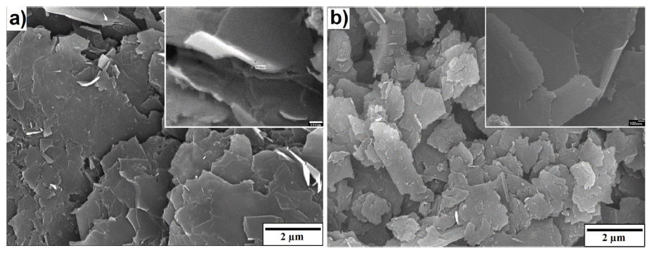
Fig. 2
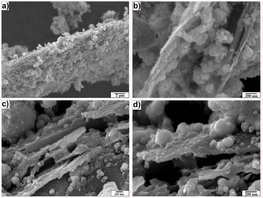
FESEM images of Ni-graphite composite after explosion (a) and (b); after heat treatment (c) and (d).
Fig. 3
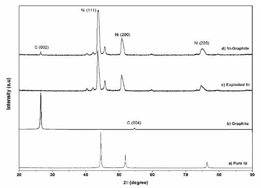
XRD pattern of a) pure Ni; b) graphite and c) the exploded Ni; d) the as-prepared Ni-graphite powders before heat treatment.
Fig. 4

XRD pattern of a) pure Ni; b) graphite and c) the exploded Ni; d) the as-prepared Ni-graphite powders after heat treatment.
Fig. 5
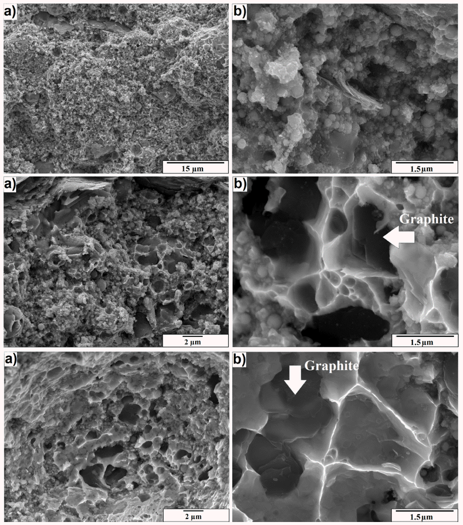
Fracture surface of the sintered samples with Low and High magnification at (a) and (b) 900 °C, (c) and (d) 1000 °C, (e) and (f) 1100 °C.
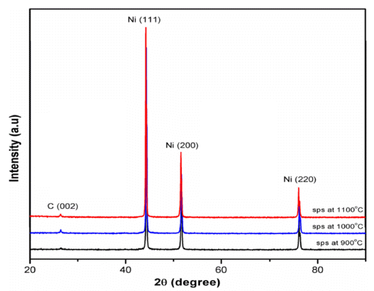
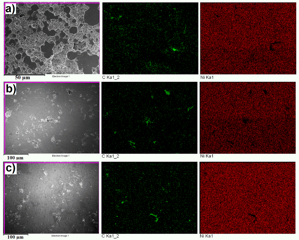
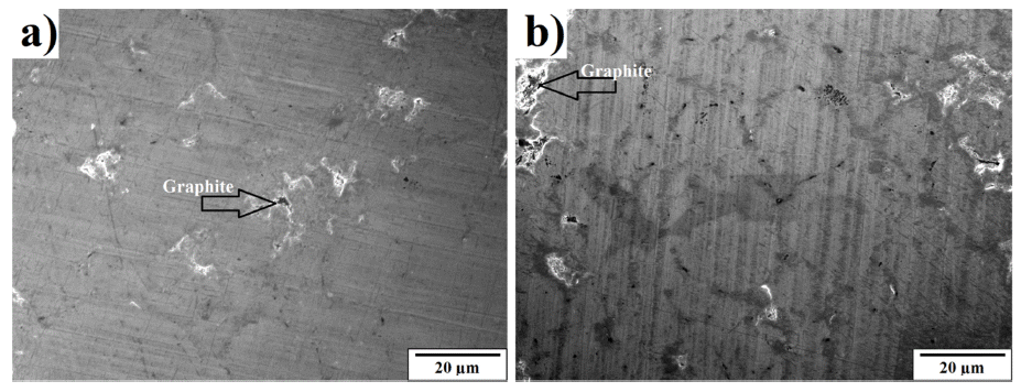
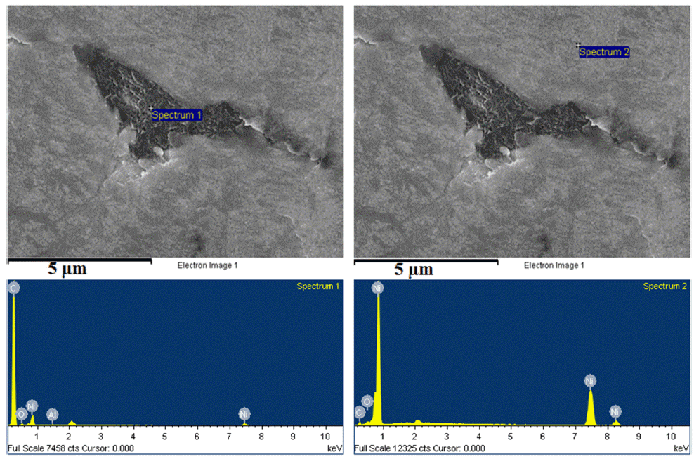
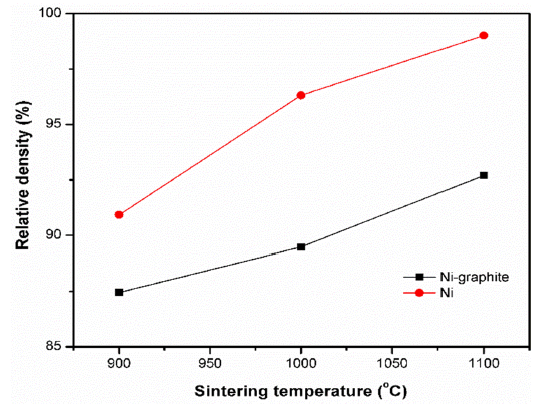

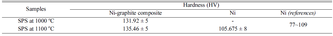
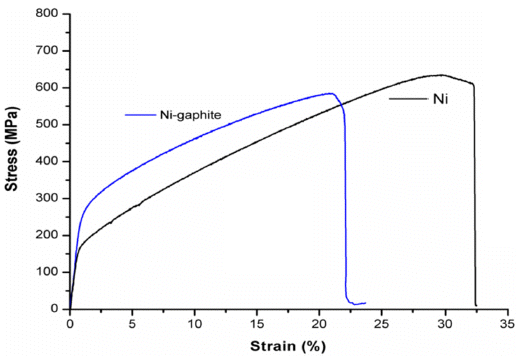
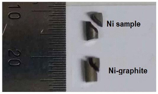
Table 3
Yield strength, ultimate strength and elongation properties of as-synthesized Ni-graphite composites and exploded Ni achieved from compression test

|
- A new processing route which consists of EEW in liquid, the ultrasonication, and the SPS methods was successfully applied in use to fabricate Ni-graphite composite.
- Ni-graphite composite powders which were synthesized using EEW in ethanol condition shows the spherical shape for Ni particles and nanosheets for graphite. Ni particles distributed and coated on the surface of graphite sheets homogeneously.
- The bulk specimen of the Ni-graphite composite was fabricated by SPS at 900 °C, 1000 °C and 1100 °C. According to the achieved results, the efficient consolidation for Ni-graphite composite was sintering at 1100 °C for 10 minutes under vacuum condition and a pressure of 50 MPa with a heating rate of 50°/min.
- The sintered Ni-graphite composite exhibited a substantial enhancement (about is about 1.3 times higher) in microhardness and compressive yield strength (about 1.6 times higher) as compared to SPS processed exploded Ni, under similar processing conditions. The mechanical property enhancement in the Ni-graphite composite can be attributed to reinforcement effects resulting from a homogeneous distribution of graphite in Ni matrix. However, it also showed the reduction in elongation of the assintered Ni-graphite composite.
- This study presents a simple, economical approach to prepare the bulk Ni-graphite composites, which had desirable mechanical properties that could be considered to use in structural materials. It also has potentials to use for processing of other metal matrix carcbonaceous composites.
4. Conclusions
-
Acknowledgements
- This research was supported by The Leading Human Resource Training Program of Regional Neo industry through the National Research Foundation of Korea (NRF) funded by the Ministry of Science, ICT and future Planning (NRF-2016H1D5A1910587).
Acknowledgements
- 1. R. F. Sohel Rana: Woodhead Publishing (2016). .
- 2. G. Sun, X. Li, Y. Qu, X. Wang, H. Yan and Y. Zhang: Mater. Lett., 62 (2008) 703. .Article
- 3. S. R. Bakshi, D. Lahiri and A. Agarwal: Int. Mater. Rev., 55 (2010) 41. .Article
- 4. A. R. P. Singh, J. Y. Hwang, T. W. Scharf, J. Tiley and R. Banerjee: Mater. Sci. Technol., 26 (2010) 1393. .Article
- 5. S. W. Kim, W. S. Chung, K. S. Sohn, C. Y. Son and S. Lee: Korean J. Met. Mater., 47 (2009) 50. .Article
- 6. K. T. Kim, S. I. Cha, S. H. Hong and S. H. Hong: Mater. Sci. Eng. A, 430 (2006) 27. .Article
- 7. L. S. Tang and M. Mariatti: Polym. Plast. Technol. Eng., 48 (2009) 614. .Article
- 8. Y. Wang, Y. Gao, L. Sun, Y. Li, B. Zheng and W. Zhai: Results Phys., 7 (2016) 263. .Article
- 9. C. H. Hager, J. Sanders, S. Sharma and A. A. Voevodin: Wear, 267 (2009)1470. .Article
- 10. S. K. Singh, A. K. Yadav, M. J. Akhtar and K. K. Kar: Adv. Mater. Proc., 2 (2017) 2..Article
- 11. K. Sedláčková, P. Lobotka, I. Vávra and G. Radnóczi: Carbon, 43 (2005) 2192. .Article
- 12. Y. Yunasfi and W. A. Adi: Int. J. Technol., 3 (2016) 479. .Article
- 13. Q. Li, G. Z. Zeng, W. F. Zhao and G. H. Chen: Synth. Met., 160 (2010) 200. .Article
- 14. A. Liu, G. E. Welsch, R. L. Mullen and D. Hazony: Metall. Mater. Trans. A, 37 (2006) 2849. .Article
- 15. Z. Ren, N. Meng, K. Shehzad, Y. Xu, S. Qu, B. Yu and J. K. Luo: Nanotechnol., 26 (2015) 065706. .ArticlePubMed
- 16. X. Xu, Z. D. Cui, S. L. Zhu, Y. Q. Liang and X. J. Yang: Surf. Coat. Technol., 240 (2014) 425. .Article
- 17. H. Zhao, L. Liu, W. Hu and B. Shen: Mater. Des., 28 (2007) 1374. .Article
- 18. Y. Yunasfi and W. A. Adi: Int. J. Technol., 3 (2016) 479. .Article
- 19. D. V. Dudina, A. V. Ukhina, B. B. Bokhonov, V. I. Mali, A. G. Anisimov, N. V. Bulina and I. N. Skovorodin: Sci. Sinter., 47 (2015) 237. .Article
- 20. L. H. Bac, J. S. Kim and J. C. Kim: Res. Chem. Intermed., 36 (2010) 795. .Article
- 21. C. Cho, Y. C. Ha, C. Kang, Y. S. Jin and G. H. Rim: J. Korean Phy. Soc., 57 (2010) 1807. .Article
- 22. S. Yamanaka, R. Gonda, A. Kawasaki, H. Sakamoto, Y. Mekuchi, M. Kuno and T. Tsukada: Mater. Trans., 48 (2007) 2506. .Article
- 23. T. Borkar, J. Hwang, J. Y. Hwang, T. W. Scharf, J. Tiley, S. H. Hong and R. Banerjee: J. Mater. Res., 29 (2014) 761. .Article
- 24. J. Y. Hwang, B. K. Lim, J. Tiley, R. Banerjee and S. H. Hong: Carbon, 57 (2013) 282. .Article
- 25. T. Borkar, H. Mohseni, J. Hwang, T. W. Scharf, J. S. Tiley, S. H. Hong and R. Banerjee: J. Alloys Compd., 646 (2015) 135. .Article
- 26. S. I. Cha, K. T. Kim, S. N. Arshad, C. B. Mo and S. H. Hong: Adv. Mater., 17 (2005) 1377. .Article
- 27. S. Suarez, F. Lasserre and F. Mücklich: Mater. Sci. Eng. A, 587 (201) 381. .Article
- 28. A. Agarwal, S. R. Bakshi and D. Lahiri: CRC press (2011). .
- 29. S. C. Tjong: Adv. Eng. Mater., 9 (2007) 639. .Article
- 30. N. Hansen: Scr. Mater., 51 (2004) 801. .Article
- 31. T. Borkar and R. Banerjee: Mater. Sci. Eng. A, 618 (2014) 176. .Article
- 32. L. Reinert, M. Zeiger, S. Suarez, V. Presser and Mücklich: Rsc Adv., 5 (2015) 95149. .Article
Figure & Data
References
Citations
Citations to this article as recorded by 
- Top-down strategies for achieving high-quality graphene: Recent advancements
Arpana Agrawal
Journal of Industrial and Engineering Chemistry.2025; 142: 103. CrossRef - Electrodeposition of nickel-titanium dioxide coatings and powders from aqueous sulfate solutions
Tazhibayeva Aigerim Shotaevna, Bayeshova Azhar Kospanovna, Bayeshov Abduali, Osińska Małgorzata
Polyhedron.2025; 277: 117571. CrossRef
 Cite this Article


Spark Plasma Sintering of the Ni-graphite Composite Powder Prepared by Electrical Explosion of Wire in Liquid and Its Properties


Fig. 1
FE-SEM images of graphite nanoplates (a) after EEW, and (b) after sonication.
Fig. 2
FESEM images of Ni-graphite composite after explosion (a) and (b); after heat treatment (c) and (d).
Fig. 3
XRD pattern of a) pure Ni; b) graphite and c) the exploded Ni; d) the as-prepared Ni-graphite powders before heat treatment.
Fig. 4
XRD pattern of a) pure Ni; b) graphite and c) the exploded Ni; d) the as-prepared Ni-graphite powders after heat treatment.
Fig. 5
Fracture surface of the sintered samples with Low and High magnification at (a) and (b) 900 °C, (c) and (d) 1000 °C, (e) and (f) 1100 °C.
Fig. 6
XRD patterns of SPS Ni-graphite composite specimens sintered at 900 °C, 1000 °C and 1100 °C.
Fig. 7
FESEM and EDS mapping images of sintered specimens at a) 900 °C, b) 1000 °C and c) 1100 °C.
Fig. 8
High magnification FE-SEM images of sintered specimen at a) 1000 °C and b) 1100 °C.
Fig. 9
EDS profiles of the dark and white region phases in the sintered composite sample.
Fig. 10
Relative density of samples sintered at various temperatures.
Fig. 11
Stress-strain curves of as-synthesized Ni-graphite composite and exploded Ni.
Fig. 12
Photographs of the shear fracture in the specimen after compression test.
Fig. 1
Fig. 2
Fig. 3
Fig. 4
Fig. 5
Fig. 6
Fig. 7
Fig. 8
Fig. 9
Fig. 10
Fig. 11
Fig. 12
Spark Plasma Sintering of the Ni-graphite Composite Powder Prepared by Electrical Explosion of Wire in Liquid and Its Properties
Table 1
Density of sintered samples at various sintering temperature
Table 2
The Vickers microhardness of the sintered Ni-graphite composites
Table 3
Yield strength, ultimate strength and elongation properties of as-synthesized Ni-graphite composites and exploded Ni achieved from compression test
Table 1
Table 2
Table 3
TOP
