
Articles
- Page Path
- HOME > J Powder Mater > Volume 32(1); 2025 > Article
-
Research Article
- The Effect of a CNT/MnO2 Nanoparticle Composite–Based Multi-Shell Typed Electrode for a Fiber Supercapacitor (FSC)
- Yeonggwon Kim1, Hyung Woo Lee1,2,3,*
-
Journal of Powder Materials 2025;32(1):30-36.
DOI: https://doi.org/10.4150/jpm.2024.00416
Published online: February 28, 2025
1Department of Nano Fusion Technology, Pusan National University, Busan 46241, Republic of Korea
2Department of Nanoenergy Engineering, Pusan National University, Busan 46241, Republic of Korea
3Research Center of Energy Convergence Technology, Pusan National University, Busan 46241, Republic of Korea
- *Corresponding author: Hyung Woo Lee E-mail: LHW2010@pusan.ac.kr
© The Korean Powder Metallurgy & Materials Institute
This is an Open Access article distributed under the terms of the Creative Commons Attribution Non-Commercial License (http://creativecommons.org/licenses/by-nc/4.0/) which permits unrestricted non-commercial use, distribution, and reproduction in any medium, provided the original work is properly cited.
- 2,779 Views
- 27 Download
Abstract
- Fiber supercapacitors have attracted significant interest as potential textile energy storage devices due to their remarkable flexibility and rapid charge/discharge capabilities. This study describes the fabrication of a composite fiber supercapacitor (FSC) electrode through a multi-shell architecture, featuring layers of carbon nanotube (CNT) conductive shells and MnO2 nanoparticle active shells. The number of layers was adjusted to assess their impact on FSC energy storage performance. Increasing the number of shells reduced electrode resistance and enhanced pseudocapacitive characteristics. Compared to the MnS@1 electrode, the MnS@5 electrode exhibited a high areal capacitance of 301.2 mF/cm2, a 411% increase, but showed a higher charge transfer resistance (RCT) of 701.6 Ω. This is attributed to reduced ion diffusion and charge transfer ability resulting from the thicker multi-shell configuration. These results indicate that fine-tuning the quantity of shells is crucial for achieving an optimal balance between energy storage efficiency and stability.
- The necessity of developing highly flexible energy storage systems has been emphasized by the increasing demand for wearable devices, including smartwatches and sensors. Fiber supercapacitors (FSCs) have garnered substantial attention as a result of their superior charge-discharge rates and high power density in comparison to conventional lithium batteries [1, 2]. Additionally, their inherent flexibility, in conjunction with their exceptional physical and chemical stability, enables their integration into textile-based devices. This renders them particularly well-suited for applications in peripheral technologies that necessitate high mobility [3].
- Supercapacitors are typically categorized into two groups based on the fundamental energy storage mechanisms and the nature of the electrode materials. Electric double-layer capacitors (EDLCs) store energy tangibly by forming an electric double layer on the electrode surface, utilizing carbon-based materials as electrodes. Conversely, pseudocapacitors utilize electrode materials such as metal oxides or conductive polymers to store energy through faradaic reactions, which are similar to the mechanisms of batteries. Although EDLCs demonstrate exceptional cycling stability, they are characterized by a relatively low capacitance. Conversely, pseudocapacitors exhibit a higher capacitance but a relatively lower cycling stability. In order to overcome these constraints and improve the stability and capacitance of supercapacitors, there has been a significant amount of research focused on the development of hybrid supercapacitors. These devices consist of carbon electrodes with EDLC characteristics and electrodes with pseudocapacitive properties [1-4].
- Carbon nanotube (CNT), which consist of carbon atoms organized in a cylindrical formation, have attracted considerable interest as electrode materials for electric double-layer capacitors because of their outstanding electrical and mechanical characteristics [5, 6]. When formed into one-dimensional fiber structures, carbon nanotube fibers demonstrate significant porosity, an extensive surface area, and remarkable flexibility, rendering them exceptionally appropriate for use in textile-based devices.
- Manganese dioxide (MnO2), a transition metal oxide exhibiting pseudocapacitive properties, has garnered significant attention as an electrode material for supercapacitors due to its high capacitance, affordability, and eco-friendliness [7]. Nonetheless, the fundamental low conductivity of metal oxides poses a considerable obstacle in the design of supercapacitor electrodes. Elevating the mass loading of MnO2 on electrodes frequently results in increased resistance, which may subsequently diminish overall capacitance. Therefore, it is crucial to create supercapacitor electrodes that sustain high conductivity while allowing for increased MnO2 loading to enhance energy storage performance [8].
- Recent studies have explored the development of hybrid FSC electrodes by combining carbon nanotube fibers with MnO2 to achieve both stability and high capacitance. A commonly proposed structure to maintain conductivity is the core-shell configuration, where a thin MnO2 film is deposited on the surface of carbon nanotube fibers [8, 9]. However, this approach has limitations, including a restricted MnO2 mass loading capacity and insufficient electrochemical activity of the core carbon nanotube fiber due to the low conductivity of the oxide shell [9].
- To address these challenges, this study presents the development of a hybrid FSC electrode (FSCE) with a multi-shell structure, where conductive CNT shells and MnO2 active shells are layered onto a CNT fiber core electrode. The conductive shells were fabricated using a dry-spun CNT film coating process, while the MnO2 active shells, composed of MnO2 nanoparticles, were created via a simple chemical bath deposition (CBD) method. The evaluation of the energy storage properties of the CNT/MnO2 composite electrodes was conducted by modifying the number of layered shells. This approach demonstrates the potential for enhanced cycling stability and charge storage performance, making it a promising candidate for FSC applications.
1. Introduction
- 2.1 Materials
- Ethyl alcohol (anhydrous, 99.5%), 0.2 M Potassium permanganate aqueous solution (KMnO4), Sodium Sulfate (Na2SO4, Anhydrous) were purchased from Daejung Chemicals & Metals Co. LTD.
- 2.2 Synthesis of Carbon Nanotubes and Fabrication of Carbon nano fibers
- The CNTs were synthesized using the Chemical Vapor Deposition (CVD) method. A 4-inch silicon wafer featuring a 200 nm layer of SiO2 was employed as the substrate, onto which 4 nm of aluminum oxide (Al2O3) and 2 nm of iron (Fe) were deposited using an electron beam evaporator. Acetylene served as the carbon source, and vertically aligned carbon nanotubes (VACNTs) were synthesized with heights between 300 and 400 µm at a temperature of 720°C for a duration of 30 minutes. The synthesized VACNTs underwent a dry spinning process to yield a continuous film of carbon nanotubes. Two continuous CNT films, each measuring 25 mm in width, were positioned in parallel with a 5 mm gap and subjected to a rotational speed of 2,000 rpm to produce CNT fiber core electrodes with an approximate diameter of ~60 µm.
- 2.3 Fabrication of Multi-Shell Typed Fiber Supercapacitor Electrodes
- The multi-shell FSCE were fabricated by layering conductive shells made of CNTs and active shells composed of MnO2 nanoparticles, as illustrated in the graphical schematic shown in Fig. 1. The CNT conductive shells were applied to the surface of the MnO2 active shells, and electrodes were fabricated and analyzed based on the number of active shells layered onto the core electrode (denoted as MnS@N). All electrodes were designed with the outermost layer consisting of the active shell.
- The MnO2 nanoparticle active shells were deposited using the CBD method, while the conductive shells were applied via dry coating of CNT films. The active shell was deposited by maintaining tension on the CNT fiber core electrodes while they were immersed in 120 mL of ethanol. Subsequently, 20 mL of a 0.2 M potassium permanganate hydroxide solution was added to the ethanol, initiating a chemical reaction for 30 minutes.
- After the MnO2 deposition was complete, the fiber electrodes were sequentially rinsed with ethanol and deionized (DI) water and then dried at room temperature for 30 minutes. The CNT conductive shells were coated by securing the MnS@N fiber electrodes onto a rotating device, rotating at 3,000 rpm, while the CNT film was moved across the electrode surface at a speed of 25 mm/s. As depicted in Fig. 1, the CNT film was coated with continuous lines instead of a sheet, which was accomplished by adjusting the fiber's rotational speed to 3,000 rpm and setting the linear velocity of the CNT film to 25 mm/s. This process was repeated to create the FSCE with a structure of alternating active and conductive shells.
- 2.4 Characterization
- The structure of the fabricated FSCE and the verification of MnO2 nanoparticles were examined using a scanning electron microscope (SEM, Supra 25, ZEISS), which includes an integrated energy-dispersive X-ray spectroscopy (EDS) system.
- Electrochemical properties were evaluated using a three-electrode system with a potentiostat (ZIVE SP1). A Pt rod was used as the counter electrode, and Ag/AgCl served as the reference electrode. The FSCEs used for measurements were 15 mm in length and tested in a 0.5 M Na2SO4 electrolyte solution. Supercapacitor performances were assessed using cyclic voltammetry (CV), galvanostatic charge-discharge (GCD), and electrochemical impedance spectroscopy (EIS). For the EIS measurements, the frequency range was set between 1 MHz and 10 mHz.
- 2.5 Evaluation of Electrochemical Performance
- The areal capacitance of the electrodes was calculated using two methods. The capacitance as a function of scan rate (V/s) was determined using Equation (1). It was derived by dividing the CV curve area (∫IdV) by the scan rate (v), the external surface area of the electrode (Asur), and the voltage window (ΔV).
- Capacitance based on discharge current values was calculated from the results of GCD analysis using Equation (2). The capacitance was determined by dividing the discharge current (II) and discharge time (Δt) by the external surface area of the electrode (Asur) and the voltage window (ΔV) [10].
2. Experimental Section
- 3.1 Morphology of CNT/MnO2 Multi-Shell Electrodes
- The active shell composed of MnO2 nanoparticles was deposited via the chemical reaction between ethanol (C2H5OH) and potassium permanganate (KMnO4), as described in Equation 3. When potassium permanganate is mixed with ethanol, ethanol is oxidized to acetic acid (CH3COOH), while MnO4- ions are reduced to MnO2, which subsequently precipitates onto the carbon nanotube (CNT) fiber electrode [11, 12].
- The SEM images in Fig. 2(a) and (b) confirm the uniform deposition of MnO2 nanoparticles on the surface of the CNT fiber core electrode. Additionally, in the second active shell, denoted as MnS@2, which was fabricated after layering the CNT conductive shell, MnO2 nanoparticles were observed to be evenly distributed across the CNT strands on the electrode surface.
- For the conductive shell fabricated via CNT film coating, the shell thickness was carefully controlled to remain within approximately 10%, as shown in Fig. 2(e). This was crucial to mitigate the adverse effects of increased shell thickness on ion diffusion and charge transfer from the electrode surface to the core, which could significantly impact the energy storage performance.
- MnO2 nanoparticles generated via the CBD are deposited onto the CNT fiber in the form of precipitates. Even with extended reaction times during CBD, the precipitates tend to settle at the bottom of the reaction chamber rather than penetrating the dense CNT bundles. As a result, deposition occurs exclusively on the surface of the CNT fiber. Therefore, to enhance the MnO2 nanoparticle loading, the introduction of a CNT conductive shell, which provides additional precipitation sites, is essential.
- As demonstrated by the EDS analysis in Fig. 3, coating the conductive shell adds new CNT bundles to the electrode surface. These additional bundles create new deposition sites for MnO2 nanoparticles, facilitating the subsequent loading of MnO2 active shells onto the electrode surface.
- 3.2 Electrochemical Performance Evaluation of Supercapacitor Electrodes
- FSCEs were fabricated by sequentially layering MnO2 active shells and CNT conductive shells in varying numbers. Electrodes featuring one (MnS@1), three (MnS@3), and five (MnS@5) MnO2 active shells were prepared, and their electrochemical performances were evaluated and compared.
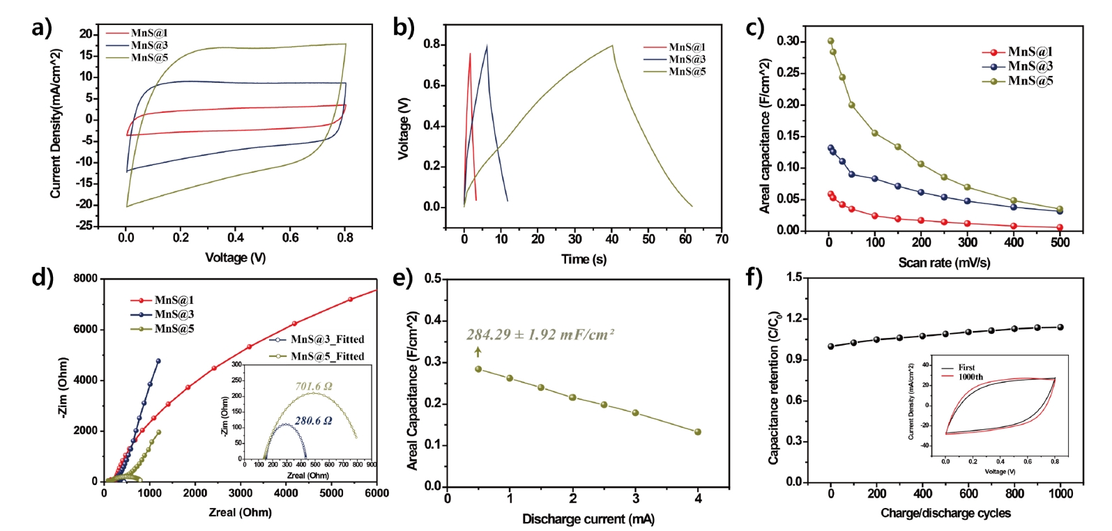
- The cyclic voltammetry (CV) results in Fig. 4(a) show rectangular-like CV curves, whereas the charge-discharge curves illustrated in Fig. 4(b) exhibit triangular profiles. The observed patterns indicate a behavior typical of an electric double layer, which is a result of non-faradaic reactions, alongside the fast redox reactions associated with pseudocapacitive MnO2. This illustrates the combined energy storage features of MnO2 pseudocapacitance along with the electric double-layer properties of CNTs [9, 13].
- From the CV curves measured at a scan rate of 50 mV/s within a voltage range of 0–0.8 V, it was observed that the current density increases proportionally with the number of MnO2 active shells. This increase is attributed to the higher surface area of the electrode and the increased mass loading of MnO2 nanoparticles resulting from the additional layers.
- At a scan rate of 5 mV/s, the MnS@5 electrode exhibited the highest areal capacitance of 301.2 mF/cm2, significantly higher than that of MnS@1 (58.9 mF/cm2) and MnS@3 (131.87 mF/cm2). This substantial improvement underscores the benefits of increasing the number of active shells, enhancing both the electrode's surface area and MnO2 nanoparticle mass loading.
- Pseudocapacitive electrodes exhibit a decrease in ion diffusion capability as the scan rate increases, and the extent of this reduction varies depending on the electrochemical properties of the electrode [14, 15].
- As shown in Fig. 4(c), when the scan rate was increased from 5 mV/s to 500 mV/s, the areal capacitance decreased for all electrodes. The MnS@1 electrode showed a capacitance reduction from 5.97 mF/cm2, the MnS@3 electrode from 31.50 mF/cm2, and the MnS@5 electrode from 35.29 mF/cm2. This corresponds to decreases of 89.9%, 76.1%, and 88.4%, respectively, relative to their highest capacitance values.
- To analyze the trend of capacitance reduction, electrochemical impedance spectroscopy (EIS) was conducted, and the results are presented in the Nyquist plot in Fig. 4(d). In the high-frequency region, the intercept on the real axis represents the series resistance (RS), which reflects the resistance of the electrode itself and the interface between the electrode and the electrolyte. The semicircle in the mid-frequency region corresponds to the charge transfer resistance (RCT), while the sloping line in the low-frequency region, represented by the Warburg resistance (ZW) at a 45° angle, indicates the capacitive behavior based on its slope [16-18].
- As the number of shells increases, the intrinsic electrical resistance of the electrode decreases, and the MnO2 mass loading increases. Consequently, the RS decreases from 249.5 Ω for MnS@1 to 150.6 Ω for MnS@3, resulting in enhanced capacitive characteristics and a steeper slope in the low-frequency region. However, for MnS@5, the slope in the low-frequency region exhibits a noticeable reduction in steepness. This phenomenon is attributed to reduced ion diffusion rate between the electrolyte and the electrode due to the thick multi-shell layers [19].
- The inset in Fig. 4(d) provides fitted RCT values derived from the semicircle. The absence of a semicircle for MnS@1 indicates low RCT, suggesting that the single shell allows unimpeded charge movement within the electrode. In contrast, for MnS@3 and MnS@5, the multi-shell structure restricts charge transfer between the electrolyte and the electrode, leading to increased RCT values of 280.6 Ω and 701.6 Ω, respectively [18, 20].
- Therefore, the primary factors contributing to the reduction in capacitance at higher scan rates are identified as high electrode resistance and ZW for MnS@1, and high RCT for MnS@5.
- Fig. 4(e) shows the capacitance of the MnS@5 electrode measured at varying discharge current values, ranging from 0.5 mA to 4 mA. The capacitance retention, compared to the initial current value, was determined to be 53%, indicating that while the multi-shell structure achieves high capacitance, it exhibits limited energy storage stability.
- The charge-discharge cycle stability of the MnS@5 electrode is shown in Fig. 4(f). After 1,000 charge-discharge cycles, the capacitance of the MnS@5 electrode increased by approximately 14% compared to the initial value. This improvement is attributed to the prolonged exposure of the electrode to the electrolyte, allowing previously unpenetrated electrolyte ions to diffuse into the internal active shells and core fiber electrode, thereby enhancing charge transfer capability.
3. Results and Discussion
- This study involved the fabrication of multi-shell typed FSCEs through the alternate layering of conductive carbon nanotube (CNT) shells and MnO2 nanoparticle active shells onto a CNT core fiber electrode. The analysis and comparison of the electrochemical performance of the electrodes were conducted with respect to the number of shells. The MnS@5 electrode reached a peak capacitance of 301.2 mF/cm2, indicating a 411% enhancement relative to MnS@1. This illustrates that the multi-shell architecture significantly improves the mass loading of MnO2 nanoparticles and their energy storage capability. However, when the number of active shells exceeded three, the ion diffusion rate into the electrode and the charge transfer capabilities were diminished. This resulted in reduced electrochemical stability and heightened capacitance variability with alterations in scan rate. The results highlight the importance of fine-tuning the number of shells to achieve an optimal balance between capacitance and stability. The optimization of these systems is essential for the progression of hybrid supercapacitor devices and for broadening their potential applications in upcoming energy storage technologies.
4. Conclusion
-
Funding
This work was supported by a 2-Year Research Grant of Pusan National University.
-
Conflict of Interest
The authors declare no competing financial interests or personal relationships.
-
Data Availability Statement
All data, including the data used in manuscript, will be made available on request.
-
Author Information and Contribution
Yeongwon Kim: Ph. D. researcher, conceptualization, experiment, writing–original draft; Hyung Woo Lee: Professor, design of concept and supervision.
-
Acknowledgement
None.
Article information


- 1. K. M. Joseph, H. J. Kasparian and V. Shanov: Energies, 15 (2022) 6506.Article
- 2. Q. Huang, D. Wang and Z. Zheng: Adv. Energy Mater., 6 (2016) 1600783.Article
- 3. S. T. Senthilkumar, Y. Wang and H. Huang: J. Mater., 3 (2015) 20863.Article
- 4. J. Wen, B. Xu, Y. Gao, M. Li and H. Fu: Energy Storage Mater., 37 (2021) 94.Article
- 5. J. Gong, Y. Tang, H. Yang and P. Yang: Chem. Eng. Sci., 134 (2015) 217.Article
- 6. Z. Lu, R. Raad, F. Safaei, J. Xi, Z. Liu and J. Foroughi: Front. Mater., 6 (2019) 138.Article
- 7. Z. Li, Y. Mi, X. Liu, S. Liu, S. Yang and J. Wang: J. Mater. Chem. A, 21 (2011) 14706.Article
- 8. C. Choi, J. A. Lee, A Y. Choi, Y. T. Kim, X. Lepró, M. D. Lima, R. H. Baughman and S. J. Kim: Adv. Mater., 26 (2014) 2059.Article
- 9. C. Choi, K. M. Kim, K. J. Kim, X. Lepró, G. M. Spinks, R. H. Baughman and S. J. Kim: Nat. Commun., 7 (2016) 13811.Article
- 10. S. Akbulut, M. Yilmaz, S. Raina, S.-H. Hsu and W. P. Kang: Diamond Relat. Mater., 74 (2017) 222.Article
- 11. X. Li and B. Wei: Nano Energy, 1 (2012) 479.Article
- 12. T. Gu and B. Wei: Nanoscale, 7 (2015) 11626.Article
- 13. J. Cherusseri, K. S. Kumar, N. Choudhary, N. Nagaiah, Y. Jung, T. Roy and J. Thomas: Nanotechnology, 30 (2019) 202001.ArticlePDF
- 14. S. Alkhalaf, C. K. Ranaweera, P. K. Kahol, K. Siam, H. Adhikari, S. R. Mishra, F. Perez, B. K. Gupta, K. Ramasamy and R. K. Gupta: J. Alloys Compd., 692 (2017) 59.Article
- 15. Z. K. Ghouri, N. A. M. Barakat, A.-M. Alam, M. Park, T. H. Han and H. Y. Kim: Int. J. Electrochem. Sci., 10 (2015) 2064.Article
- 16. J. Gamby, P. L. Taberna, P. Simon, J. F. Fauvarque and M. Chesneau: J. Power Sources, 101 (2001) 109.Article
- 17. Z. Fan, J. Yan, T. Wei, L. Zhi, G. Ning, T. Li and F. Wei: Adv. Funct. Mater., 21 (2011) 2366.Article
- 18. M. Y. Perdana, B. A. Johan, M. Abdallah, M. E. Hossain, M. A. Aziz, T. N. Baroud and Q. A. Drmosh: Chem. Rec., 24 (2024) e202400007.Article
- 19. G. Singh, Y. Kumar and S. Husain: J. Energy Storage, 31 (2020) 101660.Article
- 20. L. Cui, L. Huang, M. Ji, Y. Wang, H. Shi, Y. Zuo and S. Kang: J. Power Sources, 333 (2016) 118.Article
References
Figure & Data
References
Citations
 ePub Link
 Cite this Article
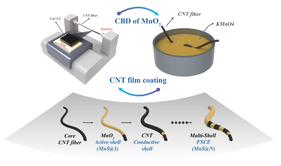


Fig. 1.
Fig. 2.
Fig. 3.
Fig. 4.
TOP
