Articles
- Page Path
- HOME > J Korean Powder Metall Inst > Volume 25(6); 2018 > Article
-
ARTICLE
- A Separator with Activated Carbon Powder Layer to Enhance the Performance of Lithium-Sulfur Batteries
- Duc-Luong Vu, Jae-Won Lee*
-
Journal of Korean Powder Metallurgy Institute 2018;25(6):466-474.
DOI: https://doi.org/10.4150/KPMI.2018.25.6.466
Published online: November 30, 2018
Department of Energy Engineering, Dankook University, Cheonan 31116, Republic of Korea
- *Corresponding Author : Jae-Won Lee, TEL: +82-41-550-3682, FAX: +82-41-559-7914, E-mail: jwlee7@dankook.ac.kr
• Received: December 18, 2018 • Revised: December 24, 2018 • Accepted: December 27, 2018
© The Korean Powder Metallurgy Institute. All rights reserved.
- 838 Views
- 4 Download
- 2 Crossref
Abstract
- The high theoretical energy density (2600 Wh kg−1) of Lithium-sulfur batteries and the high theoretical capacity of elemental sulfur (1672 mAh g−1) attract significant research attention. However, the poor electrical conductivity of sulfur and the polysulfide shuttle effect are chronic problems resulting in low sulfur utilization and poor cycling stability. In this study, we address these problems by coating a polyethylene separator with a layer of activated carbon powder. A lithium-sulfur cell containing the activated carbon powder-coated separator exhibits an initial specific discharge capacity of 1400 mAh g−1 at 0.1 C, and retains 63% of the initial capacity after 100 cycles at 0.2 C, whereas the equivalent cell with a bare separator exhibits a 1200 mAh g−1 initial specific discharge capacity, and 50% capacity retention under the same conditions. The activated carbon powder-coated separator also enhances the rate capability. These results indicate that the microstructure of the activated carbon powder layer provides space for the sulfur redox reaction and facilitates fast electron transport. Concurrently, the activated carbon powder layer traps and reutilizes any polysulfides dissolved in the electrolyte. The approach presented here provides insights for overcoming the problems associated with lithium-sulfur batteries and promoting their practical use.
- Lithium-sulfur (Li-S) batteries have been investigated as promising energy-storage devices for electric power because of their high theoretical energy density (2600 Wh kg−1) and specific capacity (1672 mAh g−1) [1-5]. Using sulfur is also advantageous because of its low cost, natural abundance, and environmental friendliness as a cathode material [1, 3, 4, 6]. However, sulfur-cathode commercialization has been impeded by many issues that need to be studied further. The degree of utilization in sulfur cathodes is limited due to their low Coulombic efficiency and fast capacity fading. More seriously, the poor reversibility of sulfur due to the dissolution of lithium polysulfides (Li2Sx, 2 < x ≤ 8) and the large volumetric expansion of sulfur during lithiation to Li2S result in a limited cycle life for Li–S batteries [7-9].
- In attempts to solve these problems, many researchers have studied various electrodes, electrolytes, and separators for Li-S batteries over near decades. Cathode research has mainly focused on modification, including wrapping in graphene [10], forming sulfur/carbon composites [11-13], doping with metal oxide nanoparticles [14-16], and coating with conductive polymers [17, 18] to improve conductivity of cathode, prevent the dissolution of lithium polydisulfides, and trap polysulfides. In comparison with the number of Li-S-battery electrode and electrolyte studies, there has been less investigation into the effects of preventing the separator shuttle effect. The separator plays an important role in enhancing the safety of lithium batteries by physically separating the positive and negative electrodes, whilst still allowing the movement of lithium ions through the liquid electrolyte during cycling via a porous membrane structure [19]. Porous polyolefin membranes, such as microporous polypropylene (PP) and polyethylene (PE), are the most widely used separators for lithium batteries because of their excellent properties, including chemical stability, mechanical strength, and low cost [19, 20]. However, these separators have a hydrophobic surface and low surface energy, which results in poor wettability by polar liquid electrolytes and increases the internal battery resistance. Recently, several researchers have used modified separators and their approaches are listed in Table 1 [20-24]. Notably, activated carbon powders (ACPs) prepared from biomass materials have proved promising as electrode materials in electrochemical energy-storage systems due to their high performance, low cost, and natural abundance [25, 26]. Porous activated carbons normally possess a large micropore/mesopore volume with a hierarchical porous structure [27]. This hierarchical structure consisting of multiple levels of pore size is beneficial for adsorbing the lithium polysulfides that limit the cycling stability of Li-S batteries [28]. Here, we report the use of ACP from coconut shells as a coating layer on a PE separator [29]. The effects of the ACP coating on the electrochemical performance of a Li-S battery were studied in detail.
Introduction
- 2.1 Preparation of ACP-coated separator
- ACP from coconut shells was provided by Cathay. Co. Ltd. and used after drying in an oven at 120oC for 24 h. A coating slurry was prepared by mixing ACP and polyvinylidene fluoride (PVDF, 8 wt %) in a 90:10 (by weight) ratio using N-methyl-2-pyrrolidone (NMP) as a solvent. The slurry was coated onto a 14 μm thick bare PE separator with using a doctor blade. The ACP-coated separator was dried in a vacuum oven for 24 h at 60°C to completely remove the NMP.
- 2.2 Materials Characterization
- Nitrogen adsorption-desorption isotherms were measured at 77 K using nitrogen sorption apparatus (Micromeritics ASAP 2020), and surface areas were calculated using the Brunauer-Emmett-Teller (BET) method. In a BET measurement the gas, usually nitrogen, adsorption of a sample is measured as a function of pressure. The morphology and elemental composition of samples were characterized using scanning electron microscopy (SEM, Hitachi S4700 and JEOL JSM 820) combined with energy dispersive spectroscopy (EDS, OXFORD 7593-H, as an SEM-instrument attachment).
- 2.3 Electrochemical Characterization
- Cathodes were fabricated using a slurry of elemental sulfur (Sigma Aldrich), Ketjen Black 600JD (Akzonobel), and PVDF binder (KF 1300, KUREHA) with a mass ratio of 60:20:20 dispersed in NMP. The electrodes were prepared by coating the slurry on aluminum foil using a doctor blade and then drying at 50oC for 24 h under a nitrogen atmosphere, followed by roll-pressing prior to use. For electrochemical measurements, 2032 coin-type cells were fabricated using the aforementioned cathode and a lithium-metal anode. Two types of PE separator –bare and ACP-coated– were compared. The electrolyte was a solution of 1 M lithium bis (trifluoromethanesulfone) imide (LiTFSI) and 0.1 M LiNiO3 dissolved in a 1:1 volume mixture of 1,3-dioxolane (DOL) and dimethoxymethane (DME). The cells were prepared in an argon-filled glove box in which the oxygen and moisture contents were maintained below 2.0 ppm.
- Galvanostatic charge-discharge tests were performed using a cycler (PNE Solution, KOREA) at different current densities in a potential range of 1.5–3.0 V (vs. Li+/ Li). Cyclic voltammetry (CV) measurements were conducted using an electrochemical analyzer (Bio-logic, VSP, USA) in a voltage range of 1.5–3.0 V at a scan rate of 0.1 mV s−1. Impedance spectra were recorded by applying an AC voltage with an amplitude of 5 mV in a frequency range of 1 MHz–500 μHz. All electrochemical tests were performed at 25 °C.
- After the electrochemical tests, the cells were disassembled in an argon-filled glove box to investigate the morphology of and elemental distribution on the electrode surface by SEM and EDS, respectively. The cathodes and separators were washed with propylene carbonate (PC) to remove any lithium salt and then further dried in the glove box prior to analysis.
Experimental
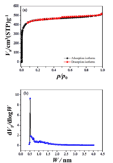
- SEM was used to characterize the ACP morphology (Figure 1), which consisted of flake-like particles whose surfaces were full of irregular cavities and slit-shaped micro/mesopores. Nitrogen adsorption-desorption curves provide qualitative information on the adsorption mechanism and porous structure of carbonaceous materials [30]. The nitrogen adsorption-desorption isotherm and pore size distribution, calculated using a DFT (density functional theory) model assuming a slit-shaped geometry, for ACP are shown in Figure 2. Nitrogen adsorption isotherms typically show three regions with increasing relative pressure. The first region at low relative pressures of less than 0.05 consists of a sharp increase in adsorption with increasing relative pressure, which is associated with adsorption or condensation in small micro/mesopores. The adsorbed volume then slowly increases with increasing relative pressure; this second region corresponds to the progressive filling of large micro/mesopores. Finally, the adsorbed volume increases abruptly near the nitrogen saturation pressure because of active capillary condensation. It is important to consider any gas volumetric flow at standard temperature and pressure (STP) (1 atm, 60 F) as molar flow when assessing performance of equipments such as compressros. The assessment shall consider converting such molar flow (V at STP) to actual V. ACP exhibited hierarchical pores, including micropores (<2 nm), mesopores (2 to 50 nm), and macropores (>50 nm). The BET specific surface area of ACP was calculated to be 1747 m2/g and its pore volume was 0.8 cm3/g, with an average pore width of about 1.83 nm. The large surface area and relatively large mesopore volume are attractive for Li-S-battery because they allow the electrolyte and Li+ ions to penetrate into the structure with ease [31].
- The surface morphology of the bare and ACP-coated separators is shown in Figure 3. The bare separator exhibits a randomly interconnected structure, with non-uniformly dispersed micropores (Figure 3a); particles with an average size of ~2 μm cover the microporous PE separator (Figure 3b). To investigate the microstructure of the ACP-coated separator more clearly, a cross section of the ACP-coated separator was analyzed using SEM and EDS, as shown in Figure 3(c). The ACP-layer thickness ranged from 18 to 20 μm, with the bare separator being around 13–14 μm thick. These SEM images further show that the ACP layer covering the top of the separator is porous, with many cavities visible between the ACP particles.
- SEM and EDS mapping were also used to characterize the surface of the ACP layer after 100 cycles at 0.2 C. Figure 4a shows that a thin layer was deposited within the interspaces and on the surface of the ACP, indicating that the ACP layer trapped polysulfides by adsorption. Elemental sulfur (S), carbon (C), oxygen (O), and fluorine (F) were found on the ACP layer, with the sulfur being uniformly distributed and exhibiting highest peak intensity (Figure 4a). Oxygen and fluorine were detected from the polymer binder. Figure 4b shows a cross-sectional SEM image of the ACP-coated separator after cycling. The ACP-layer thickness increased from 20 to 26 μm after cycling, while the PE-layer thickness was 13 to 16 μm. This increase in ACP-layer thickness is attributed to filling of the interspaces with lithium polydisulfide deposits. EDS mapping showed that the majority of lithium polysulfides in the separator were uniformly distributed within the ACP layer, with a small amount present in the PE layer (Figure 4b). This indicates that lithium polysulfides can be trapped in the micro/mesopores of ACP [19].
- The effect of using the ACP-coated separator on the performance of a Li-S cell was investigated using halfcells (Ketjen Black@S/Li metal). CVs of the cell with bare and ACP-coated separators are shown in Figure 5. The pair of redox peaks seen in the CVs of both cells indicates that the electrochemical reduction of elemental sulfur (S8) occurs in two stages during discharge. The first peak at ~2.2V (vs. Li+/ Li) corresponds to the reduction of elemental sulfur to lithium-polysulfide molecules (Li2Sn, n = 4~8). The second peak at ~1.8V is associated with the strong reduction of polysulfide ions to insoluble Li2S2 and Li2S [32]. The oxidation process in both Li–S cell occurs in a single stage, with the broad oxidation peak around 2.6V mainly attributed to the oxidation of Li2Sn (n>2) into polysulfides [32–34]. The cell comprising the ACP-coated separator shows more intense cathodic peaks, larger area, and better stability than that comprising the bare separator. This indicates that the ACP-coated separator is effective in preventing the loss of sulfur into the electrolyte and maintaining high utilization of the active sulfur in the redox reactions.
- The first charge-discharge curves of the two cells are presented in Figure 6a. All discharge curves for the two cells exhibit two potential plateau regions, corresponding to the multi-step reduction reaction of sulfur during the discharge process [9, 35]. The first charge/discharge capacities are 1413/1211 mAh g−1 and 1320/1403 mAh g−1 for the cells comprising the bare and ACP-coated separators, respectively, and they decreased to 1149/1053 mAh g−1 and 1237/1261 mAh g−1, respectively, in the second cycle. These measurements indicate that using the ACP-coated separator results in a higher specific discharge capacity, compared with using the bare separator, which we attribute to the prevention of polysulfide migration to the anode and enhanced sulfur utilization. The cycling performance of the cells was investigated at 0.2 C between 1.5 and 3.0 V, as shown in Figure 6b. Although the discharge capacity of both cells decayed drastically upon cycling, the cell utilizing the ACPcoated separator delivered better cycling performance compared with that utilizing the bare separator. The discharge capacities of 1059 mAh g−1 and 669 mAh g−1 after 1 cycle and 100 cycles, respectively, give a 63% capacity retention for the ACP-coated-separator cell. In contrast, the bare-separator cell exhibited specific discharge capacities of 864 mAh g−1 and 438 mAh g−1 after 1 cycle and 100 cycles, respectively, which corresponds to a capacity retention of only 50%.
- Figure 6c presents the rate capability of the two cells at various current densities from 0.168 to 3.35 A g−1 in a voltage range of 1.5 V to 3.0 V (vs. Li+/Li) at 25°C. After 10 cycles at 0.168 A g−1 (0.1 C), the specific discharge capacity was 1008 and 1237 mAh g−1 for the bare-separator and ACP-coated-separator cells, respectively. The discharge capacity of both cells decreased gradually with increasing current density. At a high current density of 3.35 A g−1 (2 C), the ACP-coated-separator cell retained a reversible capacity of 105 mAh g−1 after 50 cycles, while the bare-separator cell only retained a reversible capacity of 36 mAh g−1. The ACP-coated separator gave superior rate capability compared with the bare separator, with the ACP-coated-separator cell exhibiting approximately 64%, 46%, and 20% capacity retention at 0.335, 0.838, 1.68 A g−1, respectively. On returning the current density to 0.1 C, the specific capacity recovered to 502 and 826 mAh g−1 for the bare-separator and ACP-coated-separator cells, respectively. This indicates that the ACP coating provides good cycling stability during charging and discharging at different rates. The better rate capability and cycling performance may be a result of the interfacial resistance. Electrochemical impedance spectroscopy (EIS) measurements were conducted for both cells after the 50th and 100th cycles, with Nyquist plots shown in Figure 7. Both the choice of separator and the number of cycles affected the size of the semi-circle in the Nyquist plots, which is associated with the charge-transfer resistance. The interfacial resistance of both cells increased during cycling, though the ACP-coated-separator cell consistently exhibited a much smaller resistance than the bareseparator cell. We expect that the smaller interfacial resistance of the ACP-coated-separator cell contributes to its better rate capability and cycling stability.
- SEM images of the two cell cathodes following disassembly after 100 cycles are shown in Figure 8. The sulfur particles could not be observed enclosed by carbon particles prior to cycling. They were redistributed over the electrodes during cycling and were more uniformly distributed on the surface of the electrode in contact with the ACP-coated separator, compared with that in contact with the bare separator. The surface of the electrode in contact with the ACP-coated separator also appears to be smoother with a smaller population of sulfur particles, compared with that in contact with the bare separator. We attribute this to distribution of sulfur in the porous matrix of the ACP layer as well as on the electrode. In other words, the ACP layer provides additional space for the sulfur particles to reside. As seen in Figure 4, most of the sulfur on the ACP coating existed in the form of a polysulfide film. The highly porous ACP particles and the spaces among the ACP particles provide enough space for uniform distribution of the sulfur particles, in addition to providing good electronic conductivity between the sulfur particles. Finally, we expect that these advantages led to the high degree of sulfur utilization and charge/discharge reversibility seen in the ACP-coatedseparator cell.
Results and Discussion
Fig. 3
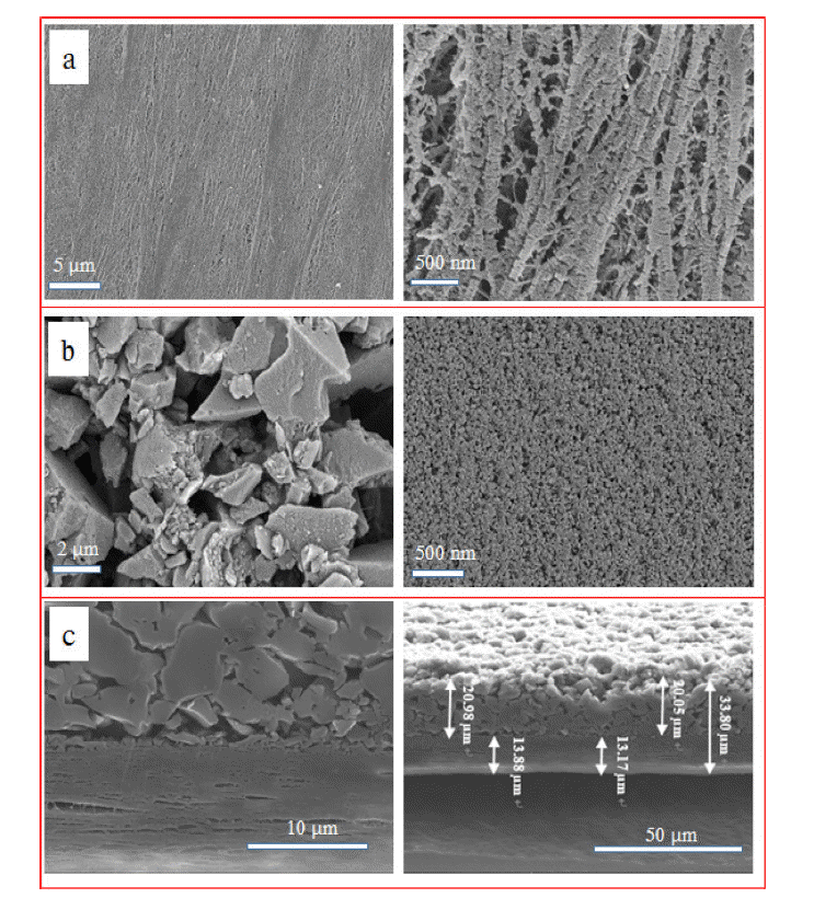
SEM images of (a) bare PE, (b) ACP-coated PE separators and (c) cross-sectional SEM images of the ACP-coated separator before cycling.

Fig. 4
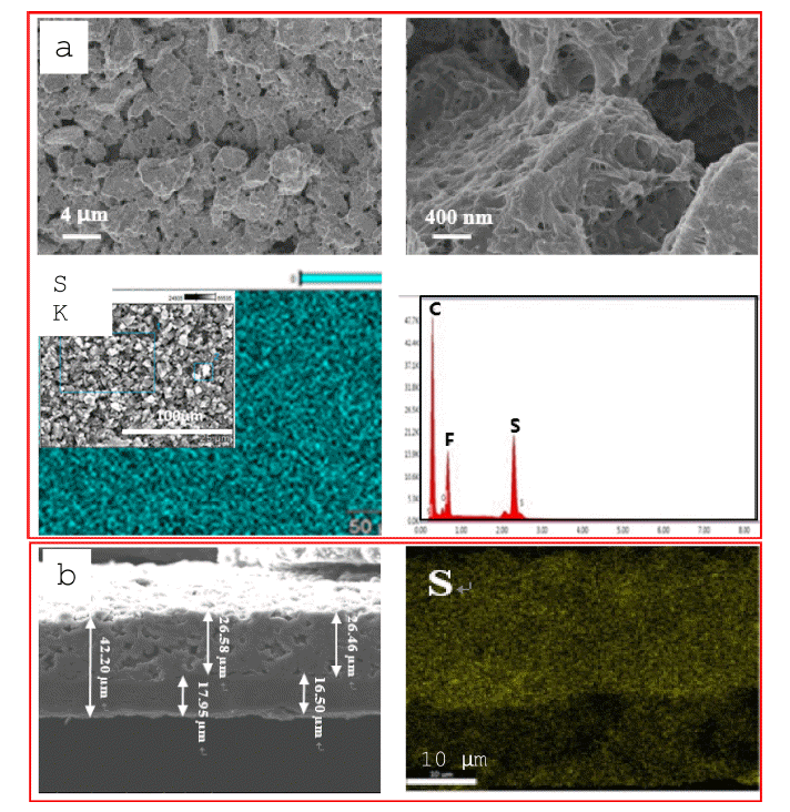
(a) SEM images and EDS map (sulfur) of the ACP-coated-separator surface and (b) cross-sectional SEM images and EDS map (sulfur) of the ACP-coated separator after 100 cycles at 0.2 C.

Fig. 5
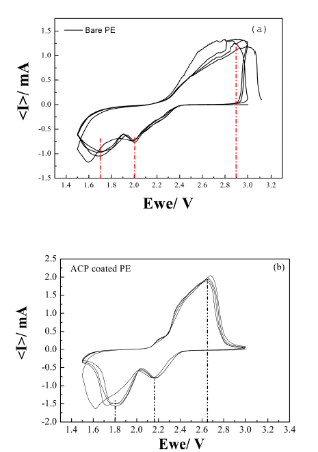
Cyclic voltammograms of a Li-S cell fabricated with (a) bare PE separator and (b) ACP-coated PE separator. The scan rate was 0.1 mV s−1.

Fig. 6

(a) First two charge/discharge profiles of Li-S cells fabricated with the bare PE and ACP-coated PE separators at a current density of 0.1 C, (b) cycling performance of Li-S cells fabricated with bare-PE and ACP-coated-PE separators at a current density of 0.2 C, (c) rate capability of Li-S cells fabricated with bare-PE and ACP-coated-PE separators at various current densities from 0.1 C to 2 C in a voltage range of 1.5-3.0 V.

Figure 7
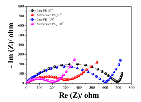
Electrochemical impedance spectra of Li-S cells fabricated with bare-PE and ACP-coated-PE separators.

- A PE separator was successfully coated with a thin layer of ACP and utilized in a Li-S cell. The electrochemical performance of this cell was compared with an equivalent cell using a bare PE separator. The ACP possessed a high surface area (SBET) of 1747 m2 g−1 and a microporous structure. The ACP-coated separator delivered much enhanced rate capability and cycling stability compared to the bare separator. The Li-S cell with the ACP-coated separator retained 246 mAh g−1 at 1 C, while the Li-S cell with the bare separator only retained 165 mAh g−1 at the same rate. The ACP-coated-separator cell also exhibited improved cycling performance, retaining a reversible capacity of 669 mAh g−1 after 100 cycles at 0.2 C. Thus, using this ACP-coated separator is a very effective way for improving the electrochemical performance of Li-S batteries. The superior cell performance is attributed to the structure of the ACP layer, which can accommodate polydisulfides and, thus, prevent them from migrating to the anode. We believe that our results will open new avenues for developing practical Li-S batteries, though further optimization of the design parameters, such as layer thickness, is still needed.
Conclusions
-
Acknowledgements
- This work was supported by the World Class 300 Project (R&D) (S2367787) of the SMBA (Korea) and the Leading Human Resource Training Program of Regional Neo industry through the National Research Foundation of Korea (NRF) funded by the Ministry of Science, ICT and future Planning (NRF-2016H1D5A1910545).
Acknowledgement
- 1. L. Ma, K. E. Hendrickson, S. Wei and L. A. Archer: Nano Today, 10 (2015) 315..Article
- 2. Y. S. Su, Y. Fu, B. Guo, S. Dai and A. Manthiram: Chem. Eur. J, 19 (2013) 8621..ArticlePubMed
- 3. J. H. Kim , D. J. Lee, H. G. Jung, Y. K. Sun, J. Hassoun and B. Scrosati: Adv Funct Mater., 23 (2013) 1076..Article
- 4. A. Manthiram, Y. Fu, S. H. Chung, C. Zu and Y. S. Su: Chem. Rev., 114 (2014) 11751..ArticlePubMed
- 5. A. Manthiram, S. H. Chung and C. Zu: Adv. Mater., 27 (2015) 1980..ArticlePubMed
- 6. H. Chen, C. Wang, W. Dong, W. Lu, Z. Du and L. Chen: Nano Lett., 15 (2015) 798..ArticlePubMed
- 7. Y. X. Yin, S. Xin, Y. G. Guo and L. J. Wan: Angew. Chem. Int. Ed., 52 (2013) 13186..ArticlePubMed
- 8. F. Wu, J. Qian, R. Chen , J. Lu, L. Li, H. Wu, J. Che n, T.Zhao, Y. Ye and K. Amine: ACS Appl. Mater. Interfaces, 6 (2014) 15542..ArticlePubMed
- 9. R. Xu, I. Belharouak, X. Zhang, R. Chamoun, C. Yu, Y. Ren, A. Nie, R. Shahbazian-yassar, J. Lu, J. C. M. Li and K. Amine: ACS Appl. Mater. Interfaces, 6 (2014) 21938..ArticlePubMed
- 10. S. Wu, R. Ge, M. Lu, R. Xu and Z. Zhang: Nano Energy, 15 (2015) 379..Article
- 11. J. J. Kim, H. S. Kim, J. H. Ahn, K. J. Lee, W. C Yoo and Y. E. Sung: J. Power Sources, 306 (2016) 617..Article
- 12. K. A. See, Y. S. Jun, J. A. Gerbec, J. K. Sprafke, F. Wudl, G. D. Stucky and R. Seshadri: ACS Appl. Mater. Interfaces, 6 (2014) 10908..ArticlePubMed
- 13. J. Schuster, G. He, B. Mandlmeier, T. E. Yim, K. T. Lee, T. Bein and L. F. Nazar: Angew. Chem. Int. Ed., 51 (2012) 3591..ArticlePubMed
- 14. Z. Li, J. Zhang and X. W. Lou: Angew. Chem. Int. Ed., 54 (2015) 12886..ArticlePubMed
- 15. R. Ponraj, A. G. Kannan, J. H. Ahn and D. W. Kim: ACS Appl. Mater. Interfaces, 8 (2016) 4000..ArticlePubMed
- 16. Z. Zhang, Q. Li, S. Jiang, K. Zhang, Y. Lai and J. Li: Chem. Eur. J., 21 (2015) 1343..ArticlePubMed
- 17. S. H. Lim, R. L. Thankamony, T. E. Yim, H. D. Chu, Y. J. Kim, J. Y. Mun and T. H. Kim: ACS Appl. Mater. Interfaces, 7 (2015) 1401..ArticlePubMed
- 18. H. Chen, W. Dong, J. Ge, C. Wang, X. Wu, W. Lu and L. Chen: Sci. Rep., 3 (2013) 1910..ArticlePubMedPMC
- 19. Y. Xiang, J. Li, J. Lei, D. Liu, Z. Xie, D. Qu, K. Li, T. Deng and H. Tang: ChemSusChem, 9 (2016) 3023..ArticlePubMed
- 20. X. Qian, L. Jin, D. Zhao, X. Yang, S. Wang, S. Wang, X. Shen, D. Rao, S. Yao, Y. Zhou and X. Xi: Electrochim. Acta., 192 (2016) 346..Article
- 21. I. Bauer, S. Thieme, J. Brückner, H. Althues and S. Kaskel: J. Power Sources, 251 (2014) 417..Article
- 22. M. S Gu, J. K. Lee, Y. I. Kim, J. S. Kim, B. Y. Jang, K. T. Lee and B. S. Kim: RSC Adv., 4 (2014) 46940..Article
- 23. G. C. Li, H. K. Jing, Z. Su, C. Lai, L. Chen, C. C. Yuan, H. H. Li and L. Liu: J. Mater. Chem. A, 3 (2015) 11014..Article
- 24. S. H. Chung and A. Manthiram : Adv. Funct. Mater., 24 (2014) 5299..Article
- 25. W. Gu and G. Yushin: Wiley Interdiscip. Rev.: Energy Environ., 3 (2014) 424..
- 26. J. Zhang, J. Xiang, Z. Dong, Y. Liu, Y. Wu, C. Xu and G. Du: Electrochim. Acta., 116 (2014) 146..Article
- 27. A. Jain, R. Balasubramanian and M. P. Srinivasan: Chem. Eng. J., 283 (2016) 789..Article
- 28. B. Zhang, M. Xiao, S. Wang, D. Han, S. Song, G. Chen and Y. Meng: ACS Appl. Mater. Interfaces, 6 (2014) 13174..ArticlePubMed
- 29. N. Yalç n and V. Sevinç: Carbon, 38 (2000) 1943. .Article
- 30. K.V. Kumar, C. V. Calahorro, J. M. Juarez, M. M. Sabio, J. S. Albero and F. R. Reinoso: Chem. Eng. J., 162 (2010)424..Article
- 31. J. G. Wang, K. Xie, B. Wei: Nano Energy, 15 (2015) 413. .Article
- 32. C. Li and Yin L: Part. Part. Syst. Char., 32 (2015) 756..Article
- 33. H. L. Wu, L. A. Huff and A. A. Gewirth: ACS Appl. Mater. Interfaces, 7 (2015) 1709..ArticlePubMed
- 34. G. Zhou, Y. Zhao, C. Zu, A. Manthiram: Nano Energy, 12 (2015) 240..Article
- 35. T. Xu, J. Song, M. L. Gordin, H. Sohn, Z. Yu, S. Chen and D. Wang: ACS Appl. Mater. Interfaces, 5 (2013) 11355..ArticlePubMed
Figure & Data
References
Citations
Citations to this article as recorded by 

- A one-step deposition method to prepare separators with carbon soot loading for lithium-sulfur battery
Yueting Zhu, Jingjing Wang, Yanshu Wang, Ying Zhu, Yixuan Li, Shicheng Zhao
Ionics.2022; 28(4): 1693. CrossRef - High thermal stability multilayered electrolyte complexes via layer-by-layer for long-life lithium-sulfur battery
Jing Wang, Yufan Li, Xianmei Deng, Lei Yan, Zhiqiang Shi
Ionics.2020; 26(11): 5481. CrossRef
A Separator with Activated Carbon Powder Layer to Enhance the Performance of Lithium-Sulfur Batteries
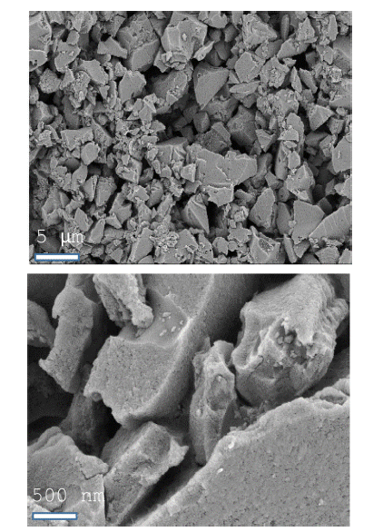


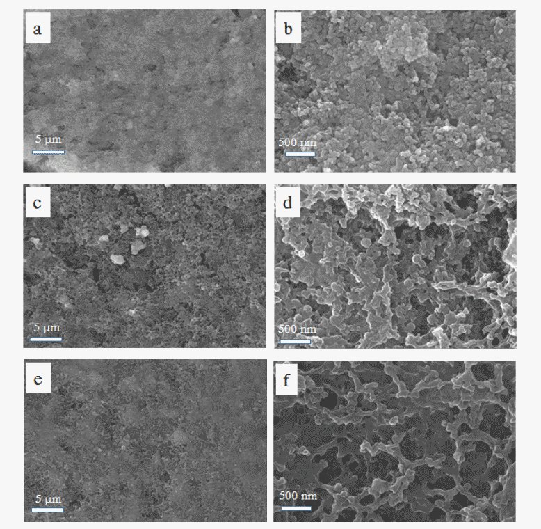
Fig. 1
SEM images of activated carbon powder (ACP).
Fig. 2
(a) Nitrogen adsorption-desorption isotherm and (b) pore size distribution for ACP.
Fig. 3
SEM images of (a) bare PE, (b) ACP-coated PE separators and (c) cross-sectional SEM images of the ACP-coated separator before cycling.
Fig. 4
(a) SEM images and EDS map (sulfur) of the ACP-coated-separator surface and (b) cross-sectional SEM images and EDS map (sulfur) of the ACP-coated separator after 100 cycles at 0.2 C.
Fig. 5
Cyclic voltammograms of a Li-S cell fabricated with (a) bare PE separator and (b) ACP-coated PE separator. The scan rate was 0.1 mV s−1.
Fig. 6
(a) First two charge/discharge profiles of Li-S cells fabricated with the bare PE and ACP-coated PE separators at a current density of 0.1 C, (b) cycling performance of Li-S cells fabricated with bare-PE and ACP-coated-PE separators at a current density of 0.2 C, (c) rate capability of Li-S cells fabricated with bare-PE and ACP-coated-PE separators at various current densities from 0.1 C to 2 C in a voltage range of 1.5-3.0 V.
Figure 7
Electrochemical impedance spectra of Li-S cells fabricated with bare-PE and ACP-coated-PE separators.
Fig. 8
SEM images of cathode surfaces used in Li-S-cells (a, b) prior to cycling and after 100 cycles with (c, d) bare-PE and (e, f) ACP-coated-PE separators at 0.2 C.
Fig. 1
Fig. 2
Fig. 3
Fig. 4
Fig. 5
Fig. 6
Figure 7
Fig. 8
A Separator with Activated Carbon Powder Layer to Enhance the Performance of Lithium-Sulfur Batteries
Table 1
Properties of Li-S batteries using various separators reported in the literature
Table 1
TOP
 KPMI
KPMI



 Cite this Article


