
Articles
- Page Path
- HOME > J Powder Mater > Volume 31(3); 2024 > Article
-
Special Article
- Trends in Materials Modeling and Computation for Metal Additive Manufacturing
- Seoyeon Jeon, Hyunjoo Choi*
-
Journal of Powder Materials 2024;31(3):213-219.
DOI: https://doi.org/10.4150/jpm.2024.00150
Published online: June 27, 2024
School of Materials Science and Engineering, Kookmin University, Seoul 02707, Republic of Korea
- *Corresponding Author: Hyunjoo Choi, TEL: +82-2-910-4287, FAX: +82-2-910-4320, E-mail: hyunjoo@kookmin.ac.kr
© The Korean Powder Metallurgy & Materials Institute
This is an Open Access article distributed under the terms of the Creative Commons Attribution Non-Commercial License (http://creativecommons.org/licenses/by-nc/4.0/) which permits unrestricted non-commercial use, distribution, and reproduction in any medium, provided the original work is properly cited.
- 3,555 Views
- 79 Download
- 2 Crossref
Abstract
-
- Additive Manufacturing (AM) is a process that fabricates products by manufacturing materials according to a three-dimensional model. It has recently gained attention due to its environmental advantages, including reduced energy consumption and high material utilization rates. However, controlling defects such as melting issues and residual stress, which can occur during metal additive manufacturing, poses a challenge. The trial-and-error verification of these defects is both time-consuming and costly.
- Consequently, efforts have been made to develop phenomenological models that understand the influence of process variables on defects, and mechanical/electrical/thermal properties of geometrically complex products. This paper introduces modeling techniques that can simulate the powder additive manufacturing process. The focus is on representative metal additive manufacturing processes such as Powder Bed Fusion (PBF), Direct Energy Deposition (DED), and Binder Jetting (BJ) method.
- To calculate thermal-stress history and the resulting deformations, modeling techniques based on Finite Element Method (FEM) are generally utilized. For simulating the movements and packing behavior of powders during powder classification, modeling techniques based on Discrete Element Method (DEM) are employed. Additionally, to simulate sintering and microstructural changes, techniques such as Monte Carlo (MC), Molecular Dynamics (MD), and Phase Field Modeling (PFM) are predominantly used.
- Additive Manufacturing (AM) is a process that fabricates products by manufacturing materials in accordance with a three-dimensional model, enabling the creation of complex three-dimensional shapes that are impossible to achieve with traditional solidification or machining methods. As a result, multiple parts can be consolidated into a single complex component, significantly reducing the number of parts used and the manufacturing processes involved. Furthermore, AM allows for the intricate and precise construction of heterogeneous materials and the flexible creation of composite or hybrid structured materials, facilitating product and business innovation. In addition, compared to traditional metal processing methods, AM can contribute to carbon neutrality by reducing energy consumption and CO2 emissions and promoting the recycling of waste materials. It represents a manufacturing process innovation by enabling the production of finished products in a single step without the need for the fabrication and assembly of numerous parts. This capability affords self-sufficiency in the production, repair, and reuse of parts, even in challenging environments such as outer space, polar regions, or remote areas where the distribution and assembly of parts are difficult [1, 2]. Due to these remarkable advantages that were previously unimaginable using conventional processes, AM is hailed as a revolution in the manufacturing industry. It is being explored for various applications, including the medical field [3], aerospace components [4], and more.
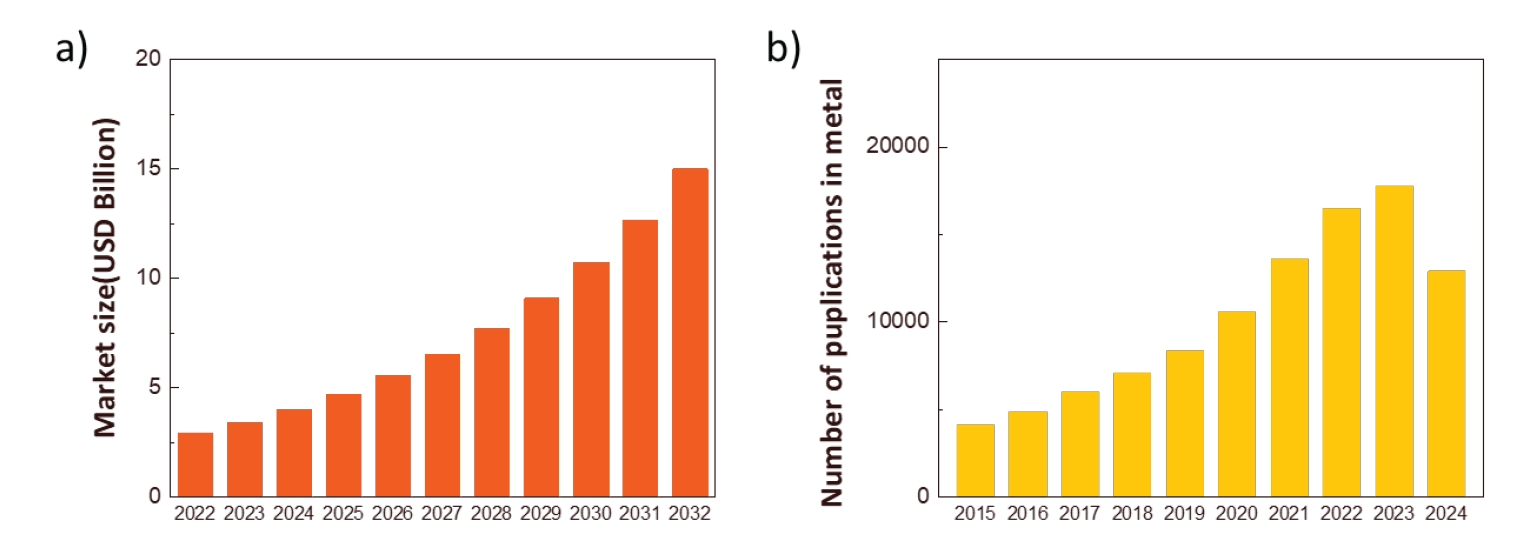
- Additive Manufacturing (AM) is widely utilized across various material fields, including polymers [5-7], ceramics [8], metals [9-11], and composites [12, 13]. As shown in Fig. 1(a), the Precedence research predicts that the global market size of metal additive manufacturing will continue to expand. Correspondingly, as depicted in Fig. 1(b), the number of research articles on metal additive manufacturing has also been increasing year by year. (The data for 2024 is collected as of May 2024, showing fewer numbers compared to 2022.) This aggregates the number of papers from 2015 to 2024 on ScienceDirect (Keyword: Metal additive manufacturing).
- According to ASTM F2792-12a by the American Society for Testing and Materials (ASTM), terms previously known as RP or rapid prototyping technologies have been standardized to 3D printing or additive manufacturing technologies. They classified the manufacturing methods into the following seven categories: Material Extrusion (ME), Material Jetting (MJ), Binder Jetting (BJ), Sheet Lamination (SHL), Vat Photo Polymerization (VPP), Powder Bed Fusion (PBF), and Direct Energy Deposition (DED) [14-18].
- In metal additive manufacturing, various defects can occur that distort the shape and degrade the quality of the product, such as melting defects, porosity, and residual stress [19]. These defects can be minimized by controlling various experimental factors such as the type and power of the heat source, scan speed and pattern, hatch spacing, and solidification and cooling conditions [20-22]. Currently, to fabricate additive manufacturing products that are free of defects, structurally robust, and reliable, different process conditions are validated through experimental trial and error, which is time-consuming and costly. Therefore, over the past two decades, efforts have been made to develop phenomenological models that quantitatively understand the influence of process variables on defects, distortions, residual stresses, microstructures, and mechanical/electrical/thermal properties of geometrically complex products. By understanding the metallurgical correlation between alloy elements, processes, microstructures, and properties, it is possible to design process variables that achieve the desired properties. Additionally, computer modeling plays a crucial role in additive manufacturing compared to other manufacturing processes because it allows for the rapid optimization of process parameters, considering both productivity (layering speed and product size) and technical compatibility (residual stress and deformation).
- Therefore, this paper aims to introduce various modeling techniques that can simulate the powder additive manufacturing process for prominent metal additive manufacturing methods such as Powder Bed Fusion (PBF) and Direct Energy Deposition (DED), as well as the increasingly popular Binder Jetting (BJ).
1. Introduction
- 2.1. Modeling of Beam-Based Metal Additive Manufacturing
- As shown in Fig. 2, PBF and DED are representative additive manufacturing processes used in metal additive manufacturing [20]. The Powder Bed Fusion (PBF) method involves spreading thin layers of metal powder, typically tens of micrometers thick, across a powder bed using a powder delivery system. A heat source then selectively fuses the powder according to the design, layer by layer. On the other hand, the Direct Energy Deposition (DED) method employs a heat source to create a molten pool on a metal substrate into which metal powder is fed. The heat source and the powder delivery nozzle move together following the design to build the 3D structure in this manner.
- Both PBF and DED can be further classified based on the type of heat source used, such as Laser Beam (L), Electron Beam (EB), Gas Tungsten Arc (GTA), Plasma Arc (PA), and Gas Metal Arc (GMA). In the PBF process, only powder can be used as the feedstock, whereas in the DED process, both powder and wire can be used. In beam-based metal additive manufacturing, various complex physical phenomena occur simultaneously, including heat absorption and transfer, molten pool formation, and solidification in the deposited material and substrate. To understand the correlations between the process, microstructure, and properties during these stages, various modeling techniques have been developed.
- Rain-drop modeling and Discrete Element Method (DEM) are representative modeling techniques used to simulate the classification process of powder materials. The Rain-drop model disregards the individual distribution process of particles and focuses solely on predicting the packing density of particles [21]. This method is primarily used in the PBF process to calculate the packing density of the powder bed [22]. In this model, the first contact of each particle is calculated following the selection of each particle's random horizontal position, then the particle is rotated in the direction that minimizes potential energy to compute the next contact point. Through this series of steps, the packing density of the powder in the powder bed can be calculated. However, the Rain-drop model has limitations in simulating the flow issues of powders and the pore structures formed within the powder layer during the powder classification process. Therefore, DEM is increasingly being applied instead of Rain-drop modeling for the modeling of material classification processes.
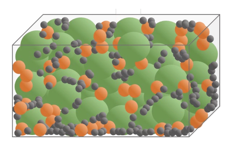
- As shown in Fig. 3, DEM, first developed by Cundall and Strack [23], is a numerical analysis technique that mechanically calculates and simulates the motion and collision of particles to model particle and granular flow. Unlike the Finite Element Method (FEM), which assumes the entire system as a continuum and derives integral solutions for continuous equations, DEM treats individual elements as discrete entities. It calculates the forces exerted on each particle at each time step under the assumption that interactions between particles occur independently, allowing for the tracking of the motion of all individual particles that make up the granular system.
- In DEM, contact forces based on contact mechanics are key elements in the interactions between particles. The time response history and energy loss of particle material are determined by the time integration of these contact forces. Contact force models generally employ a combination of the nonlinear Hertz model and Mindlin's shear model, or simplified models in the form of linear springs. With DEM modeling, it is possible to analyze the impact of various process parameters, particle-particle interactions, particle size, and shape on the spatial distribution of the powder bed (e.g., bed porosity, thickness, and surface roughness) during the powder classification process.
- To manufacture integrated products from classified powders, the powder goes through processes of heating, melting, solidification, and cooling. To quantitatively calculate deformations and potential failures in the product during this series of steps, it is essential to model the regional thermal stress history. Given the similarities between the heating, melting, and solidification processes in additive manufacturing and traditional welding processes, modeling techniques used for welding processes are often extended or adapted for additive manufacturing simulations. In beam-based metal additive manufacturing, modeling deformation and failure due to thermal stress entails linking multidimensional modeling results, ranging from macro-level elements corresponding to the heat source and components to nano- and micro-level elements representing the microstructure. This holistic integration is a significant challenge in accurately capturing the effects of thermal stress on deformation and damage in the additive manufacturing process.
- To quantitatively simulate the heat distribution within a material due to the heat source in metal additive manufacturing using a beam, accurate calculations for heat transfer considering the component's shape and material properties are crucial. Typically, in mathematical modeling of heat distribution from the heat source, the heat source is categorized as a point, line, area, or volumetric source. Point and line heat sources are often handled using the analytical solution of heat conduction equations, while area and volumetric heat sources require numerical modeling for heat transfer and fluid flow simulations.
- Laser beams, electron beams, and arcs are generally assumed to be point heat sources. By knowing the material's thermal diffusivity and the distance from the heat source, the temperature at each point can be calculated using the Rosenthal solution [24]. However, these models typically consider only conduction and disregard convective heat transfer, leading to limitations in predicting excessive temperature gradients and cooling speeds. They also do not account for fluid flow changes due to reactions between the molten pool's surface and active elements like sulfur and oxygen.
- In cases where heat transfer is dominant in one direction, extending the point-shaped heat transfer equations to line-shaped heat sources can be beneficial. Situations where a keyhole defect is formed, typically under high-power-density heat sources, can benefit from this extended line-shaped heat transfer modeling over point sources [25-27]. Energy density gradients in the diameter direction of the heat source are often assumed to follow a Gaussian distribution. In processes like Powder Bed Fusion (PBF), where the beam can penetrate deeply into the powder bed due to multiple reflections or in Directed Energy Deposition (DED) where preheating can occur along the beam path, three-dimensional volumetric heat source assumptions can be utilized for precise calculations.
- Recently, the Double Ellipsoidal Model [28] has been used to simultaneously account for conduction and convection, allowing for swift calculations while approximating the energy density distribution based on experimental melt pool shapes as double ellipsoids.
- The amount of heat absorbed in metal layer manufacturing is influenced by various factors such as the type of heat source (laser, electron beam, arc, etc.), the type and shape of materials (powder, wire, etc.). In the case of DED, since the powder deposition and heat source irradiation occur simultaneously, the powder absorbs heat while moving from the nozzle to the substrate, with 15-20% of the heat source energy being lost during this process [29]. The amount of energy absorbed by the heat source in the process of forming a molten pool after the powder is deposited on the substrate varies depending on the type and energy of the heat source, surface roughness and reflectivity of the material, local temperature of the material, and the size of the molten pool [29]. In the case of PBF, the energy absorption rate can increase due to multiple reflections within the Powder Bed, which is influenced by the beam's irradiation angle, powder size distribution and packing density, and reflectivity [30].
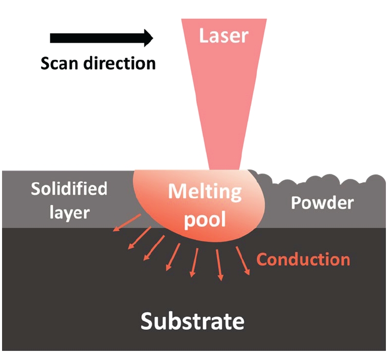
- In metal layer manufacturing, heat transfer and fluid flow can be calculated based on equations related to mass, momentum, and energy conservation. The driving forces that induce fluid flow in the molten pool in this context include: i) Marangoni Force (fluid movement in the molten pool in the tangential direction of the surface due to surface tension gradients caused by temperature gradients), ii) Lorentz (Electromagnetic) Force (movement of fluid by electromagnetic forces when using an arc or electron beam as the heat source), iii) Droplet/Powder Impact Force (force generated when sprayed powder in DED collides with the molten pool), iv) Buoyancy Force, v) Recoil Force (force driving the movement of molten metal downwards due to evaporation of alloying elements) [31]. To calculate the flow of heat and fluid during the metal layer manufacturing process, it is necessary to define the shape changes of the molten pool over time so that boundary conditions for heat and fluid transfer can be defined. Additionally, the temperature gradient on the surface of the molten pool calculated using the methods described in Sections 2.1.2.1 and 2.1.2.2 can be input as boundary conditions for heat and fluid flow during the manufacturing process, along with various driving forces for fluid flow as described above. By defining the shape of the molten pool (Fig. 4), inputting boundary conditions, and providing material information (thermal conductivity, specific heat, density, latent heat, viscosity, solidus and liquidus temperatures, etc.), the behavior of heat and fluid can be predicted as a function of time and space through finite element-based modeling.
- To simulate changes in microstructure during metal layer manufacturing processes, phase field modeling (PFM), Monte Carlo (MC), and Cellular Automata (CA) are commonly used. Among these, MC and CA are suitable for modeling mesoscale microstructures, such as the sizes and aspect ratios of multiple crystallites formed after layering, while PFM is suited for modeling microscale microstructures like solute atom concentrations, precipitates, and grain boundaries. To integrate the results of macro-scale thermal-stress modeling mentioned in Section 2.1.2 with microstructure modeling, two main methods are typically employed: i) performing thermal-stress modeling first and using the results as input parameters for microstructure modeling, and ii) concurrently conducting thermal-stress modeling and microstructure modeling with mutual information exchange. The latter method provides more precise computational results but comes with limitations of high computational time and cost [32].
- 2.2 Modeling of metal layer manufacturing without a beam
- Binder Jetting (BJ) is a representative process for metal layer manufacturing without a beam, where significant research has been conducted recently [33, 34]. In BJ, powder is selectively sprayed and manufactured by mixing it with a binder, followed by sintering to produce the final product. This section aims to introduce modeling techniques for calculating the shape and characteristics of products manufactured using this process.
- In the BJ layering process, freshly deposited powder in the Powder Bed is spread out into a single layer by a roller or blade-type spreader. The interaction between the powder and spreader, as well as inter-particle interactions, are key factors determining powder movement, often modeled using Discrete Element Method (DEM). A DEM calculates the dynamics of particle motion and collisions and mechanically simulates the flow of particles and powder, tracking the motion of individual particles by calculating the contact forces acting on them at each time interval. This allows for the analysis of various process parameters (spreading speed, spreader shape) and interactions between powder particles, as well as powder size and shape, affecting the spatial distribution of the Powder Bed (porosity, thickness, surface roughness, etc.) during powder spreading and deposition. Generally, computational results show that larger roller diameters and thinner powder layers induce higher powder compaction by applying greater pressure to the powder. It has also been discovered that slower spreading speeds can induce higher powder compaction with roller-type spreaders compared to blade-type spreaders [35, 36].
- As shown in Fig. 5, in Binder Jetting (BJ), after a layer of powder is deposited, the binder is sprayed onto the desired locations. The sprayed binder collides rapidly with the powder and deeply penetrates into the Powder Bed, transferring its kinetic energy to the powder and causing rearrangement. The interactions between the binder and powder (liquid-solid interaction) and between powder particles (solid-solid interaction) need to be simultaneously calculated. Typically, to calculate interactions between liquid and solid, methods include calculating surface tension and equilibrium forces based on differences in wettability between liquid (binder) - solid (powder) - gas (air) interfaces (Static Modeling), as well as considering changes in binder shape, flow upon contact with the powder surface along with changes in wettability and surface tension (Dynamic Modeling). Several numerical methods are used to simulate powder-binder interactions and resulting powder movements, but due to the complexity associated with various physical phenomena involved, achieving accurate modeling remains challenging with current technology [37, 38].
- The process of pore removal among powders and their coalescence during sintering, primarily driven by solid-state diffusion, is usually modeled using methods such as Monte Carlo (MC) or Molecular Dynamics (MD) [39, 40]. Recently, there has been progress in simulating sintering at the microscale using Phase Field Modeling (PFM) [41]. In PFM, a series of continuous field functions are employed to describe the microstructure, with each function representing specific physical quantities related to the microstructure (e.g., phase, chemical composition, crystal orientation). These functions calculate the evolution of microstructure over time and space based on the total free energy of the system, following Cahn-Hilliard or Allen-Cahn equations.
2. Result
2.1.1. Modeling of Material Classification Process
2.1.2. Modeling of Thermal Stress
2.1.2.1. Mathematical Modeling of Heat Source
2.1.2.2 Modeling of heat absorption
2.1.2.3 Modeling of heat transfer and fluid flow
2.1.3 Modeling of microstructure
2.2.1 Powder Behavior Modeling
2.2.2 Modeling of powder-binder interaction
- So far, various research trends in modeling techniques for simulating metal layer manufacturing processes have been introduced. Metal layer manufacturing is rapidly expanding in the market due to advantages like design freedom, high efficiency, and the possibility of producing complex-shaped products. To design optimal layering processes for different materials, various macroscopic and microscopic modeling techniques capable of simulating various physical phenomena have been proposed. Generally, Finite Element Method (FEM)-based modeling techniques are utilized to calculate thermal-stress history and resulting deformations. Discrete Element Method (DEM) modeling is used to simulate powder movement during deposition, while techniques like Monte Carlo (MC), Molecular Dynamics (MD), and Phase Field Modeling (PFM) are primarily employed to model sintering and microstructural changes. Up to now, research has mainly focused on steel-based materials, and there is a need for modeling technique studies that can be applied to a variety of metal materials. Additionally, real-time (in situ) analysis methods to validate the accuracy of models should be developed. Furthermore, research on multidimensional modeling techniques that can simultaneously calculate multidimensional physical phenomena from component-level to microstructure-level at a rapid pace is essential.
3. Conclusion
-
Conflict of Interest
H.Choi serves as an editor of the Science editing, but has no role in the decision to publish this article. Except for that, no potential conflict of interest relevant to this article was reported.
-
Author Information and Contribution
Seoyeon Jeon: MS/ Writing, Hyunjoo Choi: Professor/Supervision, review and editing.
Article information
-
Acknowledgements
- This study was financially supported by the National Research Foundation of Korea (NRF) grant funded by the Korean government (MSIP) (No. NRF-2022R1A5A1030054).


- 1. H. Lipson and M Kurman, Indianapolis, Indiana John Wiley and Sons, Inc, (2013).
- 2. A. Bandyopadhyay, K. D. Traxel, M. Lang, M. Juhasz, N. Eliaz and S. Bose: Mater. Today., 52 (2022) 207.Article
- 3. J. Giannatisis and V. Dedoussis: Int. J. Adv. Manuf. Technol., 40 (2009) 116.ArticlePDF
- 4. S. C. Altiparmak, V. A. Yardley, Z. Shi and J. Lin: Int. J. Lightweight Mater. Manuf., 4 (2021) 246.
- 5. S. Wickramasinghe, T. Do and P. Tran: Polymers., 12 (2020) 1529.Article
- 6. K. Chatterjee and T. K. Ghosh: Ghosh., 32 (2020) 1902086.
- 7. D. M. Nieto, V. C López and S. I. Molina: Addit. Manuf., 23 (2018) 79.
- 8. C. L. Cramer, E. Ionescu, M. G. Zajac, A. T. Nelson, Y. Katoh, J. J. Haslam, L. Wondraczek, T. G. Aguirre, S. Leblanc, H. Wang, M. Masoudi, E. Tegeler, R. Riedel, P. Colombo and M. M. Joladan: J. Eur. Ceram. Soc., 42 (2022) 3049.Article
- 9. S. Jeon, S Park, Y Song, J Park, H Park, B Lee and H Choi: J. Powder Mater., 30 (2023) 463.Article
- 10. S. Park, Y. Song, J. Yeo, S. Han and H. Choi: J. Powder Mater., 30 (2023) 255.Article
- 11. Y. Li and Q. Bai: Chin. J. Mech. Eng., 30 (2017) 515.ArticlePDF
- 12. W. S. Cai, H. Z. Lu, H. Z. Li, Z. Liu, H. B. Ke, W. H. Wang and C. Yang: J. Mater. Sci. Technol., 138 (2023) 80.Article
- 13. M. P. Behera, T. Dougherty and S. Singamneni: Procedia Manuf., 30 (2019) 159.Article
- 14. B. Kianian, Fort Collins, Colorado, USA Wohlers Associates, Inc, (2016).
- 15. L. Yang, K. Hsu, B. Baughman, D. Godfrey, F. Medina, M. Menon and S. Wiener, Cham Springer, (2017) 45.
- 16. ASTM, ASTM International. (2012.
- 17. J. W. Choi and H. C. Kim: J. Kor. Soc. Manuf. Process Eng., 14 (2015) 1.
- 18. I. H. Lee, H. C. Kim and D. G. Ahn: J. Kor. Soc. Precision Eng., 37 (2015) 929.Article
- 19. T. DebRoy, H. L. Wei, J. S. Zuback, T. Mukherjee, J. W. Elmer, J. O. Milewski, A.M. Beese, A. Wilson-Heid, A. De, W. Zhang and W. Zhang: Progress in Mater. Sci., 92 (2018) 112.Article
- 20. V. Manvatkar, A. De and T. DebRoy: J. Appl. Phys., 116 (2014) 124905.
- 21. V. Manvatkar, A. De and T. DebRoy: Mater. Sci. Technol., 31 (2015) 924.ArticlePDF
- 22. T. Mukherjee, H. L. Wei, A. De and T. DebRoy: Comput. Mater. Sci., 150 (2018) 369.Article
- 23. C. Körner, E. Attar and P. Heinl: J. Mater. Process. Technol., 211 (2011) 978.
- 24. B. de La Batut, O. Fergani, V. Brotan, M. Bambach and M. El Mansouri: J. Manuf. Mater. Process., 1 (2017) 3.
- 25. P. Burgardt and C. R. Heiple: Heiple: Welding J., 71 (1992) 341.
- 26. R. T. Brown: J. Laser Appl., 20 (2008) 201.ArticlePDF
- 27. Y. Javid, M. Ghoreishi and S. Shamsaei: Lasers in Engineering (Old City Publishing)., 22 (2012) 1.
- 28. P. Farahmand and R. Kovacevic: Opt. Laser Technol., 63 (2014) 154.Article
- 29. A. J. Pinkerton and L. Li: J. Eng. Manuf., 218 (2004) 363.
- 30. X. Wang, T. Laoi, J. Bonse, J.-P. Kruth, B. Lauwers and L. Froyen: Int. J. Adv. Manuf. Technol., 19 (2002) 351.ArticlePDF
- 31. T. DebToy and S. A. David: Rev. Mod. Phys., 67 (1995) 85.Article
- 32. J. H. K. Tan, S. L. Sing and W. Y. Yeong: Virtural and Physical Prototyping., 15 (2020) 87.Article
- 33. L. Ming, D. Wenchao, A. Elwany, Z. Pei and C. Ma: Manuf. Sci. Eng., 142 (2020) 090801.
- 34. J. A. Gonzalez, J. Mireles, Y. Lin and R. B Wicker: Ceram. Int., 42 (2016) 10559.Article
- 35. C. Meir, R. Weissbach, J. Winberg, W. A. Wall and A. J. Hart: J. Mater. Process. Technol., 266 (2019) 484.
- 36. G. Miao, W. Du, Z. Pei and C. Ma: Int. Manuf. Sci. Eng. Conf., 1 (2019.
- 37. H. Tan: Chem. Eng. Sci., 153 (2016) 93.Article
- 38. M. Uhlmann: J. Comput. Phys., 209 (2005) 448.Article
- 39. L. R. Madhavrao and R. Rafagopalan: J. Mater. Res., 4 (1989) 1251.Article
- 40. K. Mori, H. Matsubara and N. Noguchi: Int. J. Mechanical Sci., 46 (2004) 841.Article
- 41. W. Boettinger, J. Warren, C. Beckermann and A. Karma: Annu. Rev. Mater., 32 (2002) 163.
References
Figure & Data
References
Citations
- Review of “Integrated Computer-Aided Process Engineering Session in the 17th International Symposium on Novel and Nano Materials (ISNNM, 14–18 November 2022)”
Yeon-Joo Lee, Pil-Ryung Cha, Hyoung-Seop Kim, Hyun-Joo Choi
MATERIALS TRANSACTIONS.2025; 66(1): 144. CrossRef - Effect of Support Structure on Residual Stress Distribution in Ti-6Al-4V Alloy Fabricated by Laser Powder Bed Fusion
Seungyeon Lee, Haeum Park, Min Jae Baek, Dong Jun Lee, Jae Wung Bae, Ji-Hun Yu, Jeong Min Park
Journal of Powder Materials.2025; 32(3): 244. CrossRef
 ePub Link
 Cite this Article
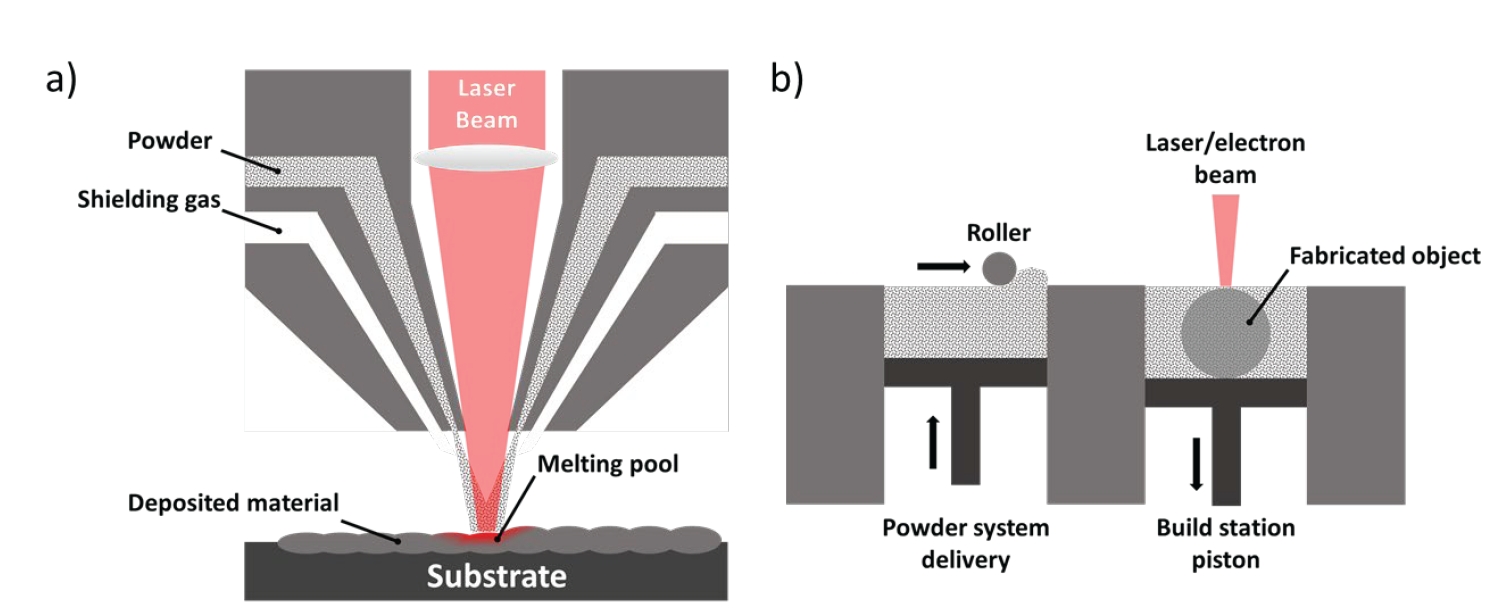


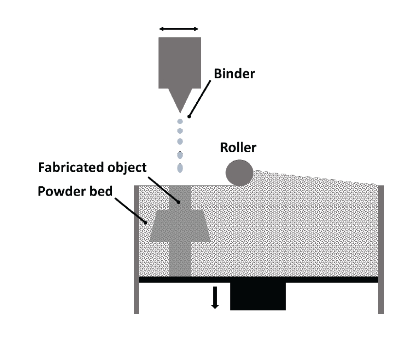


Fig. 1.
Fig. 2.
Fig. 3.
Fig. 4.
Fig. 5.
TOP
