Articles
- Page Path
- HOME > J Powder Mater > Volume 31(6); 2024 > Article
-
Research Article
- High-Temperature Steam Oxidation Behavior of Silicide- or Aluminide- Coated Mo and Nb Refractory Metals
- Woojin Lim1, Je-Kyun Baek2, JaeJoon Kim1, Hyun Gil Kim1, Ho Jin Ryu2,*
-
Journal of Powder Materials 2024;31(6):546-555.
DOI: https://doi.org/10.4150/jpm.2024.00381
Published online: December 31, 2024
1Korea Atomic Energy Research Institute, Daejeon 34057, Republic of Korea
2Department of Nuclear and Quantum Engineering, Korea Advanced Institute of Science and Technology, Daejeon 34141, Republic of Korea
- *Corresponding Author: Ho Jin Ryu E-mail: hojinryu@kaist.ac.kr
© The Korean Powder Metallurgy & Materials Institute
This is an Open Access article distributed under the terms of the Creative Commons Attribution Non-Commercial License (http://creativecommons.org/licenses/by-nc/4.0/) which permits unrestricted non-commercial use, distribution, and reproduction in any medium, provided the original work is properly cited.
- 909 Views
- 17 Download
Abstract
- Refractory materials, such as molybdenum and niobium, are potential candidates for cladding material due to their high melting temperatures and desirable mechanical properties at higher temperatures than those of zirconium alloys. However, refractory materials have low resistance to oxidation at elevated temperatures. Therefore, this study examined silicide or aluminide surface coatings as protection against rapid oxidation of refractory materials at elevated temperatures for a potential accident-tolerant fuel cladding. Silicide or aluminide layers were formed on refractory metal substrates by using the pack cementation method. The steam oxidation behavior of both coated and uncoated samples was compared by thermogravimetric analysis at 1200°C. The weight changes of the coated samples were greatly reduced than those of uncoated samples. Microstructural analyses demonstrated that the silicide and aluminide layers were oxidized to form a protective surface oxide that prevented rapid oxidation of the refractory substrate at elevated temperatures.
- Zirconium-based alloys have been used in nuclear reactors as fuel cladding for decades. They have excellent technical properties in normal operation, such as low neutron cross-section, excellent irradiation resistance, and acceptable corrosion resistance. However, at high temperatures, contemporary zirconium-based alloys face several challenges, such as low strength, relatively high rates of oxidation, and poor thermal shock resistance. In case of a nuclear reactor accident, such as Loss of Coolant Accident (LOCA), zirconium alloys lose strength above 750°C and oxidation is accelerated with high-pressure steam with temperatures above 700°C, resulting in the generation of hydrogen gas [1]. Since the Fukushima nuclear power plant accident in 2011, researchers have examined the concept of accident-resistant fuel with desired traits such as high strength and oxidation resistance even in case of a severe accident. Extensive research has been conducted on fuel cladding with a low oxidation rate in a steam atmosphere and improved thermo-mechanical properties to develop accident-tolerant fuel cladding [2]. To improve the performance of contemporary cladding systems in case of accidents, new concepts of cladding have been suggested. Refractory metals, including niobium (Nb) and molybdenum (Mo), have been suggested as potential cladding materials because of their high-temperature strength than that of zirconium alloys. Refractory metals exhibit desirable mechanical strengths at elevated temperatures. In Table 1, the mechanical properties of metals and alloys currently under study, such as Mo, and Nb are compared with those of the currently used zirconium alloy. Compared with the zirconium alloy, refractory metals have higher melting points, Young’s moduli, and thermal conductivities. Furthermore, refractory metals, have desirable high-temperature mechanical properties and acceptable neutron absorption cross-section properties because of which they can be considered as candidate materials for accident-resistant fuel-cladding.
1. Introduction
- 2.1. Refractory metals
- To conduct an oxidation test, two representative refractory metals, Mo and Nb, were prepared. Mo has been suggested as a potential cladding material because of its high-temperature strength and high melting point, but it has relatively poor oxidation resistance. Furthermore, Mo shows very destructive oxidation behavior, commonly referred to as “pest oxidation,” in the temperature range 650–750°C. In this range, molybdenum trioxide (MoO3), which is volatile, is produced as an oxidation product. The need for coating or alloying methods has been suggested if Mo is to be used as a cladding material [3-5]. Nb is also a candidate for use as a cladding material because it retains its strength at high-temperatures and has a high melting point; however, it has weak oxidation resistance at high temperatures, similar to Mo [6-8].
- Surface coatings are applied to mitigate the weak oxidation problem of Mo and Nb at elevated temperatures. The formation of continuous oxide layers has been considered an effective way to better oxidation resistance. The oxide layer on the specimen acts as a barrier for oxygen diffusion, thereby decreasing the oxidation rate. The silicon dioxide (SiO2) on the surface of metallic silicide enhances oxidation resistance. Also, aluminide coatings have been applied in high-temperature industries to improve oxidation resistance. A stable Al2O3 oxide scale can protect the underlying substrate from aggressive oxygen penetration in an oxidizing environment. Consequently, a silicide or aluminide-coating method was proposed in this study to prevent oxidation of underlying metal substrates [9-11].
- 2.2. Surface coating
- Pack cementation is a favorable coating method because it is simple, inexpensive, and produces strong bonds between the coating and substrate by inter-diffusion reactions during the process of coating. Furthermore, the method is suitable for uniformly coating materials that have complex shapes because the method uses gaseous diffusion [11-14]. The Al-rich or Si-rich coating on surfaces can form a protective oxide layer after exposure to a high-temperature oxidation environment. The substrate is buried with a powder mixture consisting of several depositional materials, called the master metal, such as Si and Al. The powder mixture also contains a halide salt and an inert filler, such as Al2O3 and SiO2. The coating layers are formed by diffusion of the mixed elements, in their vapor form, toward the substrate. The metal halides decompose and release the depositional element on the surface.
- Rod-shaped (8Φ × 100 mm) Mo and Nb substrates were provided by Phillip Trading Co., Ltd. The specimens were cut into a 2-mm thick disc using a diamond cutter and subsequently polished using SiC abrasive papers of different grits (800, 1200, 2000, and 4000 grades) to smooth the surface of the specimen. Polished specimens were then cleaned by sonicating in deionized water, and dried.
- Several types of powders, namely Al2O3 (as filler), silicon (Si), aluminum (Al), ammonium chloride (NH4Cl), and sodium fluoride (NaF) (activator), were prepared for the coating. The powder mixtures and substrates were each contained in an alumina crucible. Two mixtures, Al2O3, Si, and NH4Cl (50:30:20 wt. %), and Al2O3, Al, and NaF (50:30:20 wt. %), were used for the silicide and aluminide coatings, respectively. The crucible was installed in a tube furnace, (Fig. 1) and heat treatment was applied at 1200°C for the silicide coating and at 950°C for the aluminide coating. During the heating process, silicide and aluminide underwent the chemical interactions listed in Table 2. The crucibles were heated to the target temperatures at a rate of 10°C/min in argon gas. Several heat treatment times for 1, 3, 5, 15, and 20 h were used to change the thickness of silicide and aluminide layers.
- 2.3. Oxidation test
- Thermogravimetric analysis (TGA) is commonly adopted to analyze oxidation behavior because it provides information regarding the weight changes of samples as a function of time. Therefore, TGA was applied in this study to conduct the high-temperature oxidation tests. Figure 2 shows a schematic of the method used for conducting TGA.
- The oxidation test for disc-shaped specimens was conducted in a steam environment at 1200°C, for up to 2000 s. The steam flowed with high purity argon gas at a flow rate of 0.5 ml/min. This process was conducted for coated specimens with different duration heat treatments and uncoated, (bare), specimens.
- 2.4. Microstructural analysis before and after oxidation
- The microstructures before (as-coated specimens) and after (post-oxidized specimens) conducting the oxidation test were compared with each other. The cross sections of coated specimens were polished and the microstructures of silicide and aluminide coatings were examined. Similarly, the microstructures of samples were characterized after the TGA tests. Specimens were mounted with epoxy resin and then polished, in a direction perpendicular to the sample, with SiC abrasive paper, to observe the coating and the oxide layer after the TGA test. The morphologies of the coating and the oxide layer were examined by scanning electron microscopy (SEM). The chemical compositions of the coating and oxide layers were measured using energy dispersive X-ray spectroscopy (EDS). The crystalline structure of the coating and the oxide layers was identified using X-ray diffraction (XRD) with Cu Kα radiation (k=1.5406Å), a voltage of 40 kV and a current of 300 mA. The scan speed was 4 degrees/min from 20 to 90 degrees with a step size of 0.01 degrees.
2. Materials and Methods
- 3.1. Microstructure
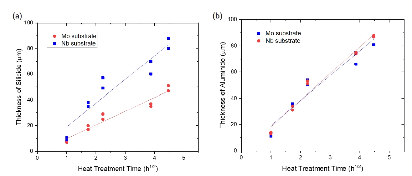
- Table 3 summarizes the changes in coating thickness with time during the pack cementation heat treatment. The growth kinetics of the coated layer exhibited the following relationship between growth rate and time:
- where x is the coating thickness (μm), k is the kinetics parameter, and the t is time (h). As shown in Fig. 3, the k values obtained from the silicide coating for Mo and Nb samples were 18.4 and 10.6 μm/h0.5, respectively. The k values calculated from growth kinetics of the aluminide coating, for Mo and Nb samples, were 19.0 and 20.3 μm/h0.5, respectively.
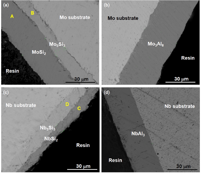
- SEM images demonstrated that the silicide coating deposited at 1200°C for 3 h was a double layer coating (Fig. 4a, 4c). The compositions of the silicide coating were measured as presented in Table 4. The Si concentration in the outer layer was approximately 67 at. %, which corresponds to stoichiometric MoSi2 and NbSi2. Stable molybdenum silicide and niobium silicides are Mo3Si, Mo5Si3, and MoSi2, and Nb3Si, Nb5Si3, and NbSi2, respectively. Only two types of silicides of Mo and Nb, Mo5Si3 and MoSi2, and Nb5Si3 and NbSi2, respectively, were detected by microstructural analysis.
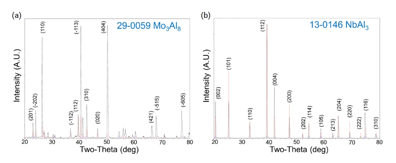
- During the pack cementation process with Al, molybdenum aluminide or niobium aluminide intermetallic compounds were generated due to the diffusion of aluminum toward the substrate. The cross-sectional image of the specimen coated with aluminide at 950°C for 3 h was analyzed by SEM. The gray phase in Fig. 4b corresponded to the Mo3Al8 coating layer based on XRD characterization as shown in Fig. 5a. In the case of the Nb substrate (Fig. 4d), the NbAl3 coating layer was identified as shown in Fig. 5b.
- 3.2. Thermogravimetric analysis
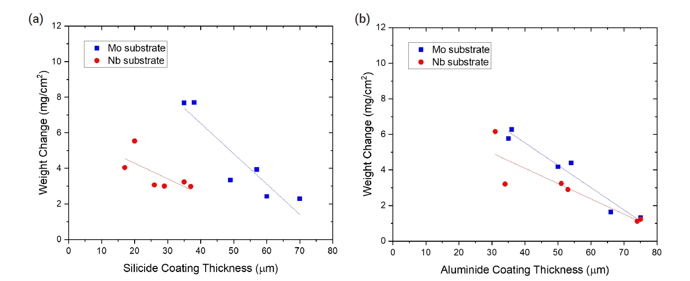
- To evaluate oxidation behavior, TGA tests were conducted at 1200°C for 2000 s. Table 5 summarizes the weight change of the uncoated and coated samples after the oxidation tests. In the case of the uncoated Mo specimens, the weight loss was very large, exceeding 120 mg/cm2, due to the volatility of MoO3. For both silicide and aluminide-coated samples, the weight change after the oxidation tests was much less. Both SiO2 and Al2O3 oxide scales provided an oxidation resistant barrier to the substrate because of their low permeability to oxygen and metal ions. The presence of the MoSi2 and Mo3Al8 coating generated the protective SiO2 and Al2O3 layers during oxidation, respectively. The weight changes decreased with the thickness of the silicide or aluminide-coating layers as shown in Fig. 6. This tendency means that the protectiveness of the coated layers was enhanced with the heat treatment time as the average thickness of the coating layers increased.
- Unlike the Mo substrate, the bare Nb substrate exhibited weight gain because niobium oxide is not volatile. Meanwhile, silicide- and aluminide-coated Nb exhibited a similar weight change compared with the Mo substrate sample. The protective mechanism was the same as that for the coated Mo substrate. The presence of the NbSi2 and NbAl3 coating generated a protective SiO2 and Al2O3 layer during oxidation, respectively. The weight change also decreased with the thickness of silicide- and aluminide-coating layers as shown in Fig. 6. The minimum weight change of 1.12 mg/cm2 after steam oxidation at 1200°C for 2000 s was obtained for the Nb specimen with an aluminide layer coated by the heat treatment of 15 h.
- 3.3. Sample morphology after oxidation test
- The SEM image of the uncoated Mo specimen after the oxidation test demonstrates that the outermost oxide layer has peeled off (Fig. 7). The remaining outer layer corresponds to MoO3, and it is hypothesized that the volatile MoO3 that formed during oxidation at elevated temperature evaporated during cooling.
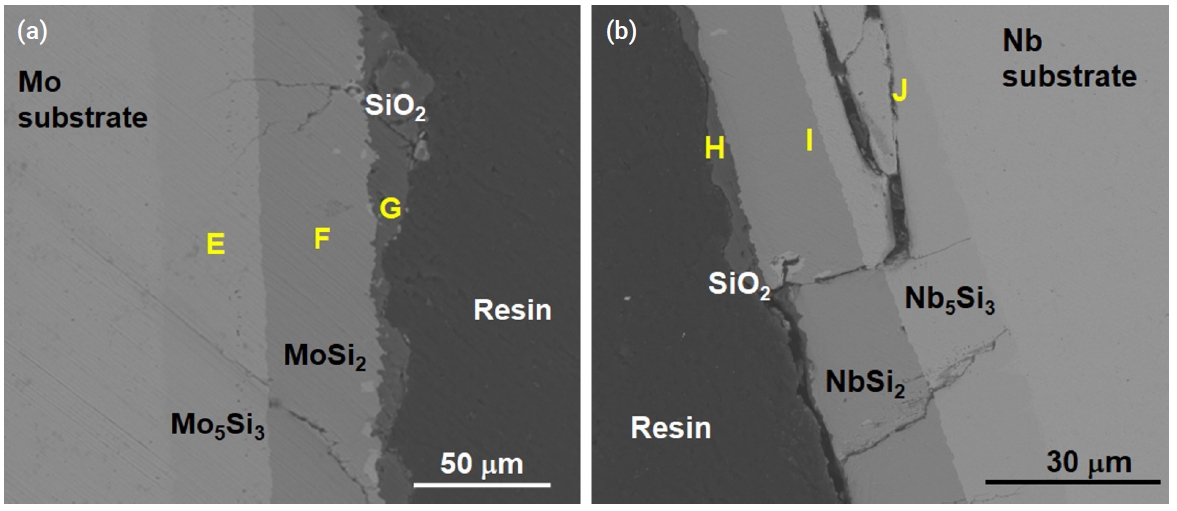
- Figure 8 shows the oxide scales on the silicide coating of the specimen after it underwent oxidation at 1200°C for 2000 s under a steam environment. A thin oxide scale was formed on the surface of each coated specimen, with thicknesses ranging between 1 and 10 μm. Table 6 summarizes the point EDS results of the samples used in SEM; the outermost layers (G, H) were composed of SiO2. Small cracks were observed in the Mo specimen and very large cracks were observed in the Nb specimen. Particularly, the delamination of the Nb5Si3 layer is remarkable as shown in Fig. 8b. Because the thermal expansion coefficients of the silicide layers and the substrate are different, this thermal stress may have initiated the formation of cracks along the coating layers.
- Figure 9 and Fig. 10 show the microstructure of oxidized aluminide-coated Mo and Nb specimens treated at 1200°C for 2000 s, respectively. When compared with the previous silicide-coated Mo specimen, the coating was not retained well as shown in Fig. 9, although the weight change in the silicide-coated specimens was similar to that in the aluminide-coated specimens after the oxidation test. It is hypothesized that the coating of the aluminide samples has poor resistance to thermal stress, low ductility, and a high thermal expansion mismatch between the substrates and the aluminide layer. Therefore, the coating became detached during the oxidation test and cooling. In the SEM image of the aluminide-coated Nb substrate, a very large area of Al2O3 and a mixture of oxides were observed along the cracks as shown in Fig. 10. In silicide-coated specimens, there was no oxide located along cracks, and this was interpreted as indicating that the crack in the silicide occurred during cooling because of the mismatch of the thermal expansion between the silicide coating and the Nb substrate. However, in aluminide-coated specimens where oxides were formed along the cracks, this was interpreted to mean that the cracks already existed during the oxidation experiment.
- Table 7 shows the thermal expansion coefficients of the coatings and substrates. The difference in the thermal expansion coefficient between Mo-Mo5Si3-MoSi2 was lower than the Nb-Nb5Si3-NbSi2 layer. The thermal expansion coefficient of Nb5Si3 was twice that of NbSi2 and three times larger than that of Nb. Therefore, large thermal mismatches occurred during cooling and this resulted in a large crack along the Nb5Si3 layer. Similarly, the difference between Nb-NbAl3 resulted in cracks along the NbAl3 layer.
- Nb silicide and aluminide demonstrated superior oxidation resistance compared to Mo silicide and aluminide, respectively. However, for future applications, it is important to consider that the larger thermal expansion mismatch of Nb silicide and aluminide, compared to other coatings, may result in the development of thermal shock cracks.
3. Results
- Refractory materials have been considered promising materials as alloy claddings because of their high creep resistance and significantly higher melting points than those of contemporary zirconium alloy claddings. To mitigate the weak oxidation behavior of refractory metals at an elevated temperature, protection through the formation of a surface coating was proposed. Silicide coating was selected to protect underlying metals against oxygen penetration because the SiO2 on the surface of the silicide can enhance oxidation resistance. Aluminide coatings have also been tested to compare the oxidation behavior with that of silicide coatings.
- Uncoated (bare) and coated specimens were exposed to an elevated temperature to analyze their oxidation resistance. Silicide- and aluminide-coated specimens showed improved oxidation resistance, exhibiting only a small weight change than that in bare specimens subjected to oxidation. Coated samples also exhibited lower weight gain than the current Zircaloy-4.
- Microstructural analysis after oxidation demonstrated that a thin and continuous SiO2 was formed on the silicide-coated specimens. The SiO2 oxide scale provided an oxidation resistant barrier, preventing the penetration of oxygen toward the underlying substrate. The weight change following oxidation was dramatically decreased in aluminide-coated specimens; the morphologies of oxidized aluminide-coated specimens were poor due to the irregular formation of Al2O3 oxide in the aluminide layers. Large cracks were found in both Nb substrates after the oxidation test due to the thermal expansion mismatches during cooling.
4. Conclusions
-
Funding
None.
-
Conflict of Interest Declaration
The authors have no conflicts of interest to declare.
-
Data Availability Statement
The dataset files are available upon request.
-
Author Information and Contribution
WJ Lim: Researcher; investigation, visualization, writing–original draft
JK Baek: PhD student; investigation
JJ Kim: Senior Researcher; investigation
HG Kim: Principal Researcher; methodology, resources
HJ Ryu: Professor; conceptualization, writing–review & editing, supervision
-
Acknowledgement
Some parts of the preliminary study have been presented in 2017 Water Reactor Fuel Performance Meeting by the same authors. This paper is based on the first author’s M.S. dissertation completed at KAIST.
Article information


| Point | Element composition (at. %) | ||
|---|---|---|---|
| Mo | Si | ||
| Mo substrate | A | 32.8 | 67.2 |
| B | 60.8 | 39.2 | |
| Nb substrate | C | 32.0 | 68.0 |
| D | 60.4 | 39.6 | |
| Point |
Element composition (at. %) |
|||
|---|---|---|---|---|
| Mo | Nb | Si | O | |
| E | 60.8 | 39.2 | ||
| F | 30.9 | 69.1 | ||
| G | 1.4 | 30.2 | 68.3 | |
| H | 1.7 | 32.1 | 66.2 | |
| I | 31.3 | 68.7 | ||
| J | 59.4 | 40.6 | ||
- 1. H. M. Chung: Nucl. Eng. Technol., 37 (2005) 327.
- 2. K. A. Terrani, J. Nucl. Mater., 501 (2018) 13.Article
- 3. A. T. Nelson, E. S. Sooby, Y. J. Kim, B. Cheng and S. A. Maloy: J. Nucl. Mater., 448 (2014) 441.Article
- 4. R. O. Suzuki, M. Ishikawa and K. Ono: J. Alloys Compd., 306 (2000) 285.Article
- 5. B. Cheng, P. Chou and Y.-J. Kim: EPJ Nuclear Sci. Technol., 2 (2016) 5.Article
- 6. B. Vishwanadh, R. H. Naina, S. Majumdar, R. Tewari and G. K. Dey: Metall. Mater. Trans. A, 44 (2013) 2258.ArticlePDF
- 7. B. P. Bewlay, M. R. Jackson, J. Zhao and P. R. Subramanian: Metall. Mater. Trans., 34A (2003) 2043.Article
- 8. M. Steinhorst and H. J. Grabke: Mater. Sci. Eng. A, 120–121 (1989) 55.Article
- 9. L. Tong, Y. Dengzun and Z. Chungen: Chinese J. Aeronaut., 23 (2010) 381.Article
- 10. C. H. Koo and T. H. Yu: Surf. Coat. Technol., 126 (2000) 171.Article
- 11. T. C. Munro and B. Gleeson: Metall. Mater. Trans. A, 27 (1996) 3761.ArticlePDF
- 12. N. Kandasamy and L. L. Seigle: Thin Solid Films, 84 (1981) 17.Article
- 13. R. Sakidja, J. S. Park, J. Hamann and J. H. Perepezko: Scr. Mater., 53 (2005) 723.Article
- 14. A. S. Khalil, F. Surfhvv, I. R. U. Wkh, L. Srzghu, F. Surfhvvlqj and W. Dqg: Microsc. Microanal., 19 (2013) 1896.Article
- 15. S. P. Chakraborty, S. Banerjee, I. G. Sharma and A. K. Suri: Development of silicide coating over molybdenum based refractory alloy and its characterization. J. Nucl. Mater., 403(1–3):(2010) 152.Article
- 16. J.A. Lembertg and R.O. Ritchie: Adv. Mater., 24 (2012) 3445.
- 17. I. L. Shabalin: Ultra-High Temperature Materials I, (2014) 451.
- 18. I. L. Shabalin: Ultra-High Temperature Materials I, (2014) 531.
- 19. S. L. Urtiga Filho, J. C. Earthman, I. Nieves, M. H. Roberts and T. P.Waked: Mater. Sci. Forum, 498 (2005) 158.Article
- 20. R. Mania, L. Stobierski, E. Godlewska, S. Koziñski and K. Mars: ISMAN, 13 (2004) 49.
- 21. F. Chu, D. J. Thoma, K. J. McClellan and P. Peralta: Mater. Sci. Eng. A, 261 (1999) 44.Article
- 22. M. L. Bauccio: ASM Engineered Materials Reference Book, Second Edition, (1994).
- 23. T. Tabaru, K. Shobu, M. Sakamoto and S. Hanada: Intermetallics, 12 (2004) 33.Article
- 24. L. Zhang and J. Wu: Scr. Mater., 38 (1997) 307.Article
References
Figure & Data
References
Citations

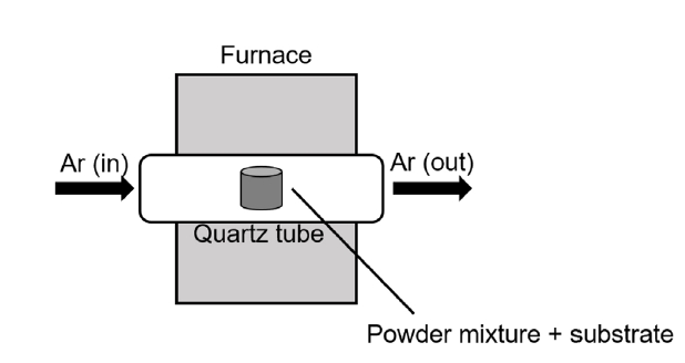
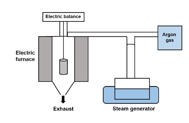


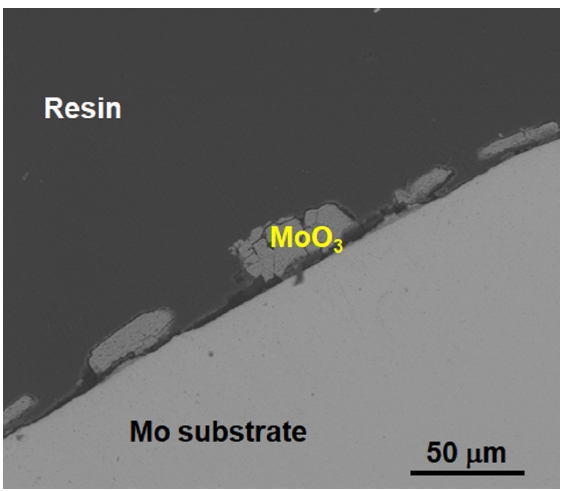


Fig. 1.
Fig. 2.
Fig. 3.
Fig. 4.
Fig. 5.
Fig. 6.
Fig. 7.
Fig. 8.
Fig. 9.
Fig. 10.
| Molybdenum | Niobium | Zirconium alloy | |
|---|---|---|---|
| Melting point (°C) | 2623 | 2477 | 1850 |
| Density (g/cm3) | 10.28 | 8.57 | 6.56 |
| Young’s Modulus (GPa) | 329 | 105 | 99.3 |
| Thermal expansion coefficient (× 10-6/K) | 5.35 | 7.3 | 6 |
| Thermal conductivity (W/m K) | 138 | 53.7 | 21.5 |
| Neutron absorption cross-section (barns) | 2.65 | 1.15 | 0.18 |
| Siliconizing |
|---|
| NH4Cl(s) → NH3(g)+ HCl(g) |
| 2NH3(g) → N2(g) + 3H2(g) |
| 4HCl(g) + Si(s) → SiCl4(g) + 4H |
| 3SiCl4(g) + Si(s) →4SiCl3(g) |
| 2SiCl3(g) + Si(s) → 3SiCl2(g) |
| SiCl2(g) + Si(s) → 2SiCl(g) |
| Si(s)+Cl2(g)+H2(g) → SiH2Cl2(g) |
| Aluminizing |
| NaF(g) + Al(s)→ AlF(g)+ Na(g) |
| 2NaF(g) + Al(s) → AlF2(g) + 2Na(g) |
| 3NaF(g) + Al(s) → AlF3(g) + 3Na(g) |
| Heat treatment time (h) | Average thickness (μm) |
|||
|---|---|---|---|---|
| Silicide |
Aluminide |
|||
| Mo | Nb | Mo | Nb | |
| 1 | 9 | 7 | 13 | 13 |
| 11 | 8 | 11 | 14 | |
| 3 | 35 | 17 | 36 | 31 |
| 38 | 20 | 35 | 34 | |
| 5 | 49 | 25 | 50 | 51 |
| 57 | 29 | 54 | 53 | |
| 15 | 60 | 35 | 66 | 75 |
| 70 | 37 | 75 | 74 | |
| 20 | 80 | 47 | 81 | 88 |
| 88 | 51 | 87 | 87 | |
| Point | Element composition (at. %) | ||
|---|---|---|---|
| Mo | Si | ||
| Mo substrate | A | 32.8 | 67.2 |
| B | 60.8 | 39.2 | |
| Nb substrate | C | 32.0 | 68.0 |
| D | 60.4 | 39.6 | |
| Specimen | Weight change (mg/cm2) |
|||||
|---|---|---|---|---|---|---|
| Silicide | Aluminide | |||||
| Mo | Bare | -121.7 | -120.1 | -100.7 | -101.1 | |
| Heat treatment time | 3 h | 7.69 | 7.71 | 6.27 | 5.77 | |
| 5 h | 3.35 | 3.94 | 4.18 | 4.40 | ||
| 15 h | 2.43 | 2.30 | 1.64 | 1.32 | ||
| Nb | Bare | 19.7 | 21.3 | 19.7 | 21.3 | |
| Heat treatment time | 3 h | 4.05 | 5.54 | 6.16 | 3.21 | |
| 5 h | 3.07 | 3.01 | 3.24 | 2.90 | ||
| 15 h | 3.24 | 2.99 | 1.23 | 1.12 | ||
| Point | Element composition (at. %) |
|||
|---|---|---|---|---|
| Mo | Nb | Si | O | |
| E | 60.8 | 39.2 | ||
| F | 30.9 | 69.1 | ||
| G | 1.4 | 30.2 | 68.3 | |
| H | 1.7 | 32.1 | 66.2 | |
| I | 31.3 | 68.7 | ||
| J | 59.4 | 40.6 | ||
| Element | Thermal expansion coefficient (×10-6/K) |
|---|---|
| Al2O3 | 8.2 (293-1273 K) |
| Mo | 6.7 (293-1973 K) |
| Nb | 8.9 (293-1973 K) |
| MoSi2 | 9.2 (298-1723 K) |
| Mo5Si3 | 5.2 (a), 11.5 (c) |
| NbSi2 | 11.7 |
| Nb5Si3 | 8.638 (a), 12.359 (c) (RT-1273 K) |
| Nb2O5 | 5.9 |
| Mo3Al8 | 6.7 |
| NbAl3 | 15 |
Table 1.
Table 2.
Table 3.
Table 4.
Table 5.
Table 6.
Table 7.
TOP
 KPMI
KPMI


 ePub Link
 Cite this Article


