
Articles
- Page Path
- HOME > J Powder Mater > Volume 31(6); 2024 > Article
-
Research Article
- Hot-Cracking Behaviors in (CoNi)85Mo15 Medium-Entropy Alloys Manufactured via Powder Bed Fusion
- Seungjin Nam1, Heechan Jung1, Haeum Park2,3, Chahee Jung1, Jeong Min Park3, Hyoung Seop Kim4,5,6,7,8, Seok Su Sohn1,2,*
-
Journal of Powder Materials 2024;31(6):537-545.
DOI: https://doi.org/10.4150/jpm.2024.00262
Published online: December 31, 2024
1Department of Materials Science and Engineering, Korea University, Seoul 02841, Republic of Korea
2Department of Advanced Future Convergence Materials, Korea University, Seoul 02841, Republic of Korea
3Department of 3D Printing Materials, Korea Institute of Materials Science (KIMS), Changwon 51508, Republic of Korea
4Department of Materials Science and Engineering, Pohang University of Science and Technology, Pohang 37673, Republic of Korea
5Graduate Institute of Ferrous and Eco Materials Technology, Pohang University of Science and Technology, Pohang 37673, Republic of Korea
6Center for Heterogenic Metal Additive Manufacturing, Pohang University of Science and Technology, Pohang 37673, Republic of Korea
7Advanced Institute for Materials Research (WPI-AIMR), Tohoku University, Sendai 980-8577, Japan
8Institute for Convergence Research and Education in Advanced Technology, Yonsei University, Seoul 03722, Republic of Korea
- *Corresponding Author: Seok Su Sohn, TEL: +82-2-3290-3271, FAX: +82-2-928-3584, E-mail: sssohn@korea.ac.kr
© The Korean Powder Metallurgy & Materials Institute
This is an Open Access article distributed under the terms of the Creative Commons Attribution Non-Commercial License (http://creativecommons.org/licenses/by-nc/4.0/) which permits unrestricted non-commercial use, distribution, and reproduction in any medium, provided the original work is properly cited.
- 2,262 Views
- 33 Download
- 1 Crossref
Abstract
- Additive manufacturing makes it possible to improve the mechanical properties of alloys through segregation engineering of specific alloying elements into the dislocation cell structure. In this study, we investigated the mechanical and microstructural characteristics of CoNi-based medium-entropy alloys (MEAs), including the refractory alloying element Mo with a large atomic radius, manufactured via laser-powder bed fusion (L-PBF). In an analysis of the printability depending on the processing parameters, we achieved a high compressive yield strength up to 653 MPa in L-PBF for (CoNi)85Mo15 MEAs. However, severe residual stress remained at high-angle grain boundaries, and a brittle µ phase was precipitated at Mo-segregated dislocation cells. These resulted in hot-cracking behaviors in (CoNi)85Mo15 MEAs during L-PBF. These findings highlight the need for further research to adjust the Mo content and processing techniques to mitigate cracking behaviors in L-PBF-manufactured (CoNi)85Mo15 MEAs.
- Since the concept of high-/medium-entropy alloys (H/MEAs) has been suggested, metallic materials have been allowed to open a new chapter with the freedom in compositional tailoring from multiple principal alloying elements [1, 2]. Based on CrCoFeNiMn [3] and CrCoNi [4] alloys, which exhibit a single solid-solution phase with a face-centered cubic (FCC) structure, various alloy systems have been explored through compositional tailoring and adding alloying elements, such as Al, Ti, and Si. This approach overcomes the limitation in mechanical properties of conventional alloys by strengthening the contribution of second-phase precipitation (i.e., L12, Sigma, Laves phases) [5–7]. Furthermore, understanding the specific roles of each alloying element enables a more systematic selection and addition of alloying elements to improve material properties. In this aspect, the addition of alloying elements with larger atomic radius has been proposed to induce severe lattice distortion into alloys, resulting in the significant effects of not only solid-solution hardening but also grain-boundaries strengthening due to increasing atomic size differences [8–10]. For instance, VCoNi MEAs have been reported to exhibit yield strength of near 1 GPa with exceptional ductility of 38% through the increase in atomic bond distance fluctuation caused by V addition [8]. Recent research has investigated the impact of adding the refractory element Mo [9]; Mo atom tended to segregate at grain boundaries in CoNiMo-based MEAs owing to the large difference in atomic radius, leading to the excellent properties due to the high Hall-Petch coefficient [11].
- On the other hand, HEAs and MEAs have inherent cost issues because of the high prices of alloying elements. In order to reduce the losses caused by subtractive manufacturing, research has focused on laser-based additive manufacturing (AM), including laser-powder bed fusion (L-PBF) and laser-direct energy deposition (L-DED). AM offers significant advancements in near-net shape production as well as microstructural aspects and resultant mechanical properties [12–16]. For instance, AMed CrCoNi MEAs [17, 18] and CrCoFeNiMn HEAs [19–22] have overcome their inherent weakness of relatively low yield strengths through the formation of refined dislocation cells. Moreover, adding Si into CrCoNi MEAs successfully enhanced the strength by introducing multiscale defects induced by AM processing [23]. Adding C to CrCoFeNiMn has also improved strengths by inducing back stress at the dislocation cells through C atom segregation within the cell structure [24, 25]. Consequently, the segregation of specific elements into the dislocation cell structure formed during AM can be utilized as a strengthening strategy, which is not feasible through conventional processing approaches. Given that the strengthening mechanism of CoNiMo MEAs primarily relies on the Hall-Petch effect, adopting AM processes, particularly L-PBF, offers significant potential for enhancing mechanical properties, wherein the rapid cooling rates of L-PBF enable to accelerate the formation of Mo-segregated dislocation-cell boundaries.
- Thus, we investigated the mechanical properties and microstructural characteristics of (CoNi)85Mo15 MEAs produced via L-PBF. After exploring their printability, optimal processing parameters were determined, and compressive tests were conducted on blocks printed under successful conditions. Although the specimens exhibited attractive mechanical peroperteis, the results of microstructural analysis revealed cracks in L-PBF (CoNi)85Mo15 MEAs. Therefore, this study focused on the underlying the cracking behavior.
1. Introduction
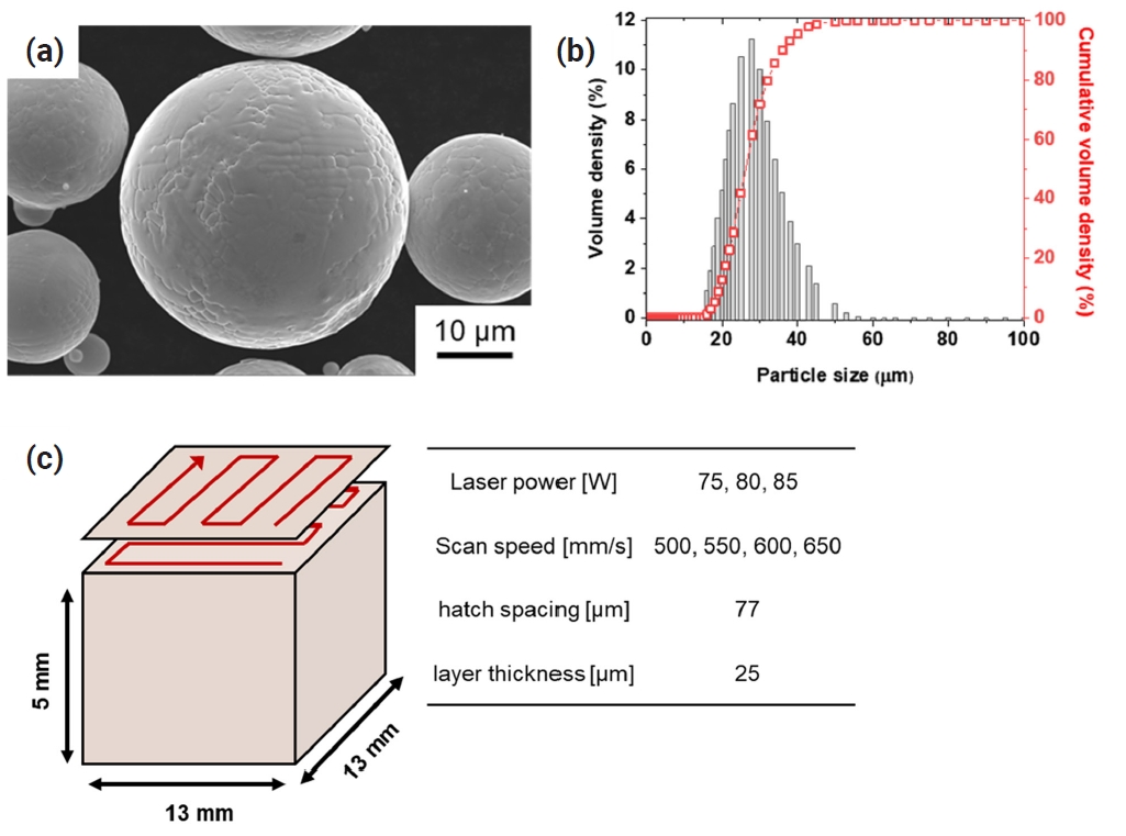
- (CoNi)85Mo15 powders were supplied by Eloi Materials Lab (EML) via gas atomization under argon atmosphere. Fig. 1(a) presents a scanning electron microscopy (SEM) image of the powders, showing the spherical morphology with minor dendritic structures on the surface owing to the rapid cooling of the powder fabrication process. Moreover, when the powder size distribution measured by particle size analyzer (PSA 1090, Anton Paar), as shown in Fig. 1(b), the powder size was ranged between 15 and 53 μm, which falls within the optimized size for L-PBF. In detail, the powder shows d10 of 18.8 um, d50 of 26.3 um, and d90 of 40.0 um with a mean size volume of 28.1 um. The terms d10, d50, and d90 stand for the particle size value, when the cumulative distribution percentage from the smallest to largest, reach 10 %, 50 %, and 90 %, respectively [26, 27]. The powder was used to print blocks of 13 × 13 × 13 mm3 on 316L stainless steel substrates through L-PBF machine of Mlab (GE additive). As described in Fig. 1(c), 90° rotation after each layer was applied to minimize the discrepancy according to the sample direction [28, 29]. The detailed processing parameters are also summarized in Fig. 1(c); the printability of L-PBF (CoNi)85Mo15 MEAs was investigated under the laser power of 75, 80, and 85 W, scan speed of 500, 550, 600, and 650 mm/s, and the fixed hatch spacing and layer thickness of 77 and 55 um, respectively.
- After the removal of the printed blocks from the substrate, the cross-section was polished using SiC papers (to 4000 grit), a diamond suspension of 1 μm, and a colloidal silica for 0.5h. The cross-sectional surface of L-PBF (CoNi)85Mo15 MEAs was observed using optical microscopy (OM, Imager D1m, ZEISS). Phase identification was carried out by using X-ray diffractometer (XRD, D/max2500, Rigaku). SEM (Quanta FEG 250, FEI) and electron backscatter diffraction (EBSD, S-4300SE, Hitachi) were used to observe the microstructures. The nano-scale microstructures were carefully investigated using a high-resolution transmission electron microscopy (HR-TEM, Titan G3, FEI) system. The TEM specimen was prepared using a dual-beam focused ion beam-SEM (FIB-SEM, Helios NanoLab 650, FEI). Finally, compression tests were conducted at a strain rate of 10−4 s−1 using an Instron-type apparatus (RB 301 UNITECH-M, R&B) to measure the yield strength of L-PBF (CoNi)85Mo15 MEAs with dimensions of 2 × 2 × 3 mm3 [30].
2. Experimental procedure
- The printability of (CoNi)85Mo15 MEAs was investigated depending on the laser power and scan speed of the L-PBF system. Fig. 2 presents the optical images showing the cross-section of L-PBF (CoNi)85Mo15 MEAs produced with varied processing parameters. While the printed blocks with the relatively low laser power of 75 W revealed a lack of fusion-based defects, the defects tended to disappear with increasing laser power. Furthermore, the porosity of the blocks was quantitatively calculated using Image J software from the images (Fig. 2) [31]. Fig. 3 shows the contour map of the porosity depending on the laser power and scan speed. While the highest value was measured in the block with the low laser power of 75 W and low scan speed of 500 mm/s, the porosity was reduced to under 1% with increasing laser power and scan speed. Thus, we determined the candidate for optimal processing parameters as 85 W in laser power and 550, 600, and 650 mm/s in scan speed.
- To evaluate the yield strength of L-PBF (CoNi)85Mo15 MEAs, we performed compressive tests on the blocks printed with scanning speeds of 550, 600, and 650 mm/s at the laser power of 85 W. Fig. 4(a) reveals their engineering strain-engineering stress curves, and the yield strength of the alloys was measured to be 620, 653, and 635 MPa, respectively. Moreover, the strength was compared to the values of AMed HEAs and MEAs reported in the literature. When DED CoCrFeMnNi was reported to have a yield strength of 346 MPa [21], DED Al0.3CoCrFeNi [32], DED AlCoCrFeNi2.1 [33], and PBF Fe40Mn20Co20Cr15Si5 [34] revealed higher values of 477, 508, and 530 MPa, respectively.
- While the major strengthening mechanism of equiatomic CoCrFeMnNi HEAs can be considered solid-solution strengthening, the addition of alloying elements (i.e., Al, Si, or N) results in additional strengthening by second phases [35–37]. Furthermore, VCoNi MEA was reported to have the largest atomic size difference among equi-atomic HEAs and MEAs with a single solid-solution phase [8, 38]. The severe lattice distortion resulted in a high yield strength of 670 MPa in DED VCoNi [39]. Similarly, PBF CrCoNi presented a high value of 692 MPa because Cr atoms could increase the lattice distortion [40]. Additionally, despite the larger atomic radius of V (164 pm) compared to Cr (128 pm), the strength of PBF CrCoNi was slightly higher than that of DED VCoNi. It might be because the cooling rate of PBF is faster, leading to a higher dislocation density and finer microstructure [41–43]. This indicates that dislocation strengthening could also be involved in PBF CrCoNi. Consequently, L-PBF (CoNi)85Mo15 MEAs (85 W – 600 mm/s) achieved a high yield strength value of 653 MPa in this study due to the Mo alloying element with a larger atomic radius (141 pm), even compared to V or Cr.The microstructural characteristics of L-PBF (CoNi)85Mo15 MEAs were investigated and summarized in Fig. 5. Fig. 5(a) exhibits the XRD pattern of the (CoNi)85Mo15, showing a single solid-solution FCC phase. One notable observation is that the peak intensity of (200) is relatively higher than (111), caused by the preferred orientation formation toward the direction of heat flux during the L-PBF. Moreover, Figure 5(b) reveals EBSD inverse pole figure (IPF) map observed at vertical direction to building direction, presenting the repeated melt pool formed during the L-PBF. The width of the melt pool was measured as approximately 75 µm. The elongated grains are aligned along the building direction from the centerline of the melt pool. The fine dislocation cell structures are presented in the cross-sectional backscattered electron (BSE) image of Fig. 5(c). The dislocation cells could be formed by the rapid solidification and aligned with a regular mean distance (~ 500 nm) and pattern in L-PBF (CoNi)85Mo15 MEAs.
- Furthermore, the dislocation cell structure is closely observed by TEM analyses. Fig. 5(d) exhibits a scanning TEM high-angle annular dark-field (STEM-HAADF) image and the corresponding elemental chemical maps of Co (blue), Ni (green), and Mo (red). It clearly shows that Mo atoms are segregated at the dislocation cells, and Mo-rich particles are precipitated at the triple junctions, as marked by white arrows. Fig. 5(e) displays a HR-TEM image, showing the precipitate. To identify the particle, the inserted fast Fourier transformation (FFT) pattern was obtained from the area marked by a white square. When the spots marked by white and red circles correspond to the matrix and particle, respectively, it indicates that the image is the projection for the (111) plane of the matrix with an FCC structure. Moreover, Mo-rich particles are considered to be a topologically-closed-packed (TCP) µ phase, wherein spots corresponding to the particle represent a (011) plane of the rhombohedral lattice (R-3m space group). Thus, we can conclude that the Mo-rich µ phase was precipitated in L-PBF (CoNi)85Mo15 MEAs owing to the Mo segregation at the dislocation cells.
- However, the enlarged EBSD analysis reveals that severe cracks are observed on the L-PBF (CoNi)85Mo15 MEAs, as shown in Fig. 6, which includes (a, d) EBSD-IPF and (b, e) Kernel average misorientation (KAM) maps obtained in the vertical and parallel directions to the building direction, respectively. Moreover, Fig. 6(c, f) presents the profile of misoreintation degree along the traces as marked by yellow arrows in Fig. 6(a, d). The black squares and red circles represent the misorientation degrees between adjacent points (i.e., Point-to-point) and the initial point (i.e., Point-to-origin) at each location. According to the EBSD results, the cracks propagated through the high-angle boundaries, where severe residual stress remained. In general, hot cracking occurs along high-angle grain boundaries, where the solidification directions of adjacent dendrite regions belonging to different grains diverge. As solidification progresses, solute atoms are rejected, and the liquid remaining at the boundaries undergoes tensile stress owing to the varied solidification directions of the surrounding matrix. This tensile stress causes the vulnerable liquid to be pulled apart, resulting in the hot-cracking phenomenon [44–46]. The presence of severe residual stress at high-angle grain boundaries, as shown in the KAM maps in Fig. 6, plays a crucial role in the initiation and propagation of hot cracks. Residual stress arises from the rapid thermal cycles inherent to the L-PBF process, accumulating at grain boundaries, particularly high-angle boundaries. Consequently, these high-angle boundaries become preferential sites for crack initiation under the rapid thermal cycles inherent to the L-PBF process.
- On the other hand, the segregation of alloying elements, such as Mo, during the rapid solidification of the L-PBF process can lead to localized regions with different features [47, 48]. Fig. 7 exhibits a STEM-HAADF image and the corresponding EDS elemental maps near cracks, clearly showing that Mo-segregation and Mo-rich precipitates are observed along the crack. Similarly, several studies have indicated that hot-cracking behaviors in Mo-containing alloys, such as Ni-based superalloys, are attributable to the formation of Mo-rich carbides at grain boundaries during the L-PBF process [49, 50]. During the L-PBF of Mo-containing alloys, the segregation of Mo at dislocation cells could be driven by two key factors of the differences in atomic radius and diffusion rates between Mo and other alloying elements. The larger atomic radius of Mo enhances its compatibility with the strained lattice surrounding dislocation cells, energetically favoring its segregation. Additionally, the lower diffusivity of Mo compared to Co and Ni may restrict its redistribution from the dislocation cells during rapid solidification. At last, Mo segregation facilitates the formation of brittle µ phases at dislocation cells, which further diminishes resistance to cracking, especially at high-angle grain boundaries that overlap with one or more sides of the dislocation cells [45, 48]. Consequently, the presence of Mo segregation, combined with severe residual stress, significantly contributes to the initiation and propagation of hot cracks at high-angle boundaries overlapping with dislocations in L-PBF (CoNi)85Mo15 MEAs. To mitigate these issues, both the alloy design adjustment of controlling the Mo content and process modifications (e.g., base plate preheating) should be further considered [51].
3. Results and Discussion
- This study investigated the printability, mechanical properties, and microstructural characteristics of (CoNi)85Mo15 MEAs manufactured via L-PBF. The optimal processing parameters were determined to be a laser power of 85 W and scan speeds of 550, 600, and 650 mm/s. L-PBF (CoNi)85Mo15 MEAs achieved a high compressive yield strength of 653 MPa, attributed to the strengthening effect of the Mo alloying element with a larger atomic radius and the refined dislocation cell structures. However, cracks were observed along the high-angle grain boundaries. This cracking is attributed to the accumulation of severe stress at the boundaries during the L-PBF process and the local reduction in resistance to cracking owing to Mo segregation and µ phase precipitation. Therefore, further research is required to adjust the Mo content and modify processing techniques to mitigate cracking behaviors in L-PBF (CoNi)85Mo15 MEAs.
4. Conclusion
-
Funding
This study was supported by the National Research Foundation of Korea (NRF) grant funded by the Korea government (MSIT) [NRF-2022R1A5A1030054].
-
Conflict of Interest Declaration
The authors declare no competing financial interests or personal relationships.
-
Data Availability Statement
All data included in this study are available upon request by contact with the corresponding author.
-
Author Information and Contribution
S. Nam: Researcher, Investigation, Visualization, Writing – original draft, H. Jung: Ph.D candidate, Methodology, Investigation, H. Park: Ph.D candidate, Resources, C. Jung: Ph.D candidate, Formal analysis, J.M. Park: Senior Researcher, Methodology, Resources, H.S. Kim: Professor, Writing – review & editing, Project administration, S.S. Sohn: Professor, Conceptualization, Writing – review & editing, Funding acquisition, Supervision.
-
Acknowledgement
None.
Article information


- 1. E.P. George, W.A. Curtin and C.C. Tasan: Acta Mater., 188 (2020) 435.Article
- 2. Z. Li, S. Zhao, R.O. Ritchie and M.A. Meyers: Prog. Mater. Sci., 102 (2019) 296.Article
- 3. B. Cantor, I. T. H. Chang, P. Knight and A. J. B. Vincent: Mater. Sci. Eng. A, 375–377 (2004) 213.Article
- 4. B. Gludovatz, A. Hohenwarter, K. V. S. Thurston, H. Bei, Z. Wu, E. P. George and R. O. Ritchie: Nat. Commun., 7 (2016) 10602.Article
- 5. H. Chang, T. W. Zhang, S. G. Ma, D. Zhao, R. L. Xiong, T. Wang, Z. Q. Li and Z. H. Wang: Mater. Des., 197 (2021) 109202.Article
- 6. H. Jung, S. Lee, T. Kang, A. Zargaran, P.-P. Choi and S. S. Sohn: J. Mater. Sci. Technol., 181 (2023) 71.Article
- 7. H. Chang, T. W. Zhang, S. G. Ma, D. Zhao, T. X. Bai, K. Wang, Z. Q. Li and Z. H. Wang: J. Alloys Compd., 896 (2022) 162962.Article
- 8. S. S. Sohn, A. Kwiatkowski da Silva, Y. Ikeda, F. Körmann, W. Lu, W.S. Choi, B. Gault, D. Ponge, J. Neugebauer and D. Raabe: Adv. Mater., 31 (2019) 1807142.Article
- 9. T. J. Jang, Y. N. Lee, Y. Ikeda, F. Körmann, J. H. Baek, H. S. Do, Y. T. Choi, H. Gwon, J. Y. Suh, H. S. Kim, B. J. Lee, A. Zargaran and S. S. Sohn: Acta Mater., 255 (2023) 119030.Article
- 10. H. Jung, G. Lee, M. Koo, H. Song, W. S. Ko and S. S. Sohn: Steel Res. Int., 94 (2023) 202200240.Article
- 11. J. Han, S. Nam, Y. T. Choi, T. J. Jang, C. Jung, S. S. Sohn, H. S. Kim and H. Choi: Int. J. Refract. Met. Hard Mater., 119 (2024) 106535.Article
- 12. S. Chen, Y. Tong and P. K. Liaw: Entropy, 20 (2018) 937.Article
- 13. A. O. Moghaddam, N. A. Shaburova, M. N. Samodurova, A. Abdollahzadeh and E. A. Trofimov: J. Mater. Sci. Technol., 77 (2021) 131.Article
- 14. Y. M. Wang, T. Voisin, J. T. McKeown, J. Ye, N. P. Calta, Z. Li, Z. Zeng, Y. Zhang, W. Chen, T. T. Roehling, R. T. Ott, M. K. Santala, P. J. Depond, M. J. Matthews, A. V. Hamza and T. Zhu: Nat. Mater., 17 (2018) 63.ArticlePDF
- 15. C. Y. Yap, C. K. Chua, Z. L. Dong, Z. H. Liu, D. Q. Zhang, L. E. Loh and S. L. Sing: Appl. Phys. Rev., 2 (2015) 041101.Article
- 16. S. P. Murray, K. M. Pusch, A. T. Polonsky, C. J. Torbet, G. G. E. Seward, N. Zhou, S. A. J. Forsik, P. Nandwana, M. M. Kirka, R. R. Dehoff, W. E. Slye and T. M. Pollock: Nat. Commun., 11 (2020) 4975.Article
- 17. J. Ge, C. Chen, R. Zhao, Q. Liu, Y. Long, J. Wang, Z. Ren and S. Yin: Mater. Des., 219 (2022) 110774.Article
- 18. B. Han, C. Zhang, K. Feng, Z. Li, X. Zhang, Y. Shen, X. Wang, H. Kokawa, R. Li, Z. Wang and P. K. Chu: Mater. Sci. Eng. A, 820 (2021) 141545.Article
- 19. J. G. Kim, J. M. Park, J. B. Seol, J. Choe, J. H. Yu, S. Yang and H. S. Kim: Mater. Sci. Eng. A, 773 (2020) 138726.Article
- 20. P. Wang, P. Huang, F. L. Ng, W. J. Sin, S. Lu, M. L. S. Nai, Z. L. Dong and J. Wei: Mater. Des., 168 (2019) 107576.Article
- 21. Z. Tong, X. Ren, J. Jiao, W. Zhou, Y. Ren, Y. Ye, E. A. Larson and J. Gu: J. Alloys Compd., 785 (2019) 1144.Article
- 22. R. Li, P. Niu, T. Yuan, P. Cao, C. Chen and K. Zhou: J. Alloys Compd., 746 (2018) 125.Article
- 23. H. Jung, J. Lee, G. H. Gu, H. Lee, S. M. Seo, A. Zargaran, H. S. Kim and S. S. Sohn: Addit. Manuf., 61 (2023) 103360.Article
- 24. J. M. Park, E. S. Kim, H. Kwon, P. Sathiyamoorthi, K. T. Kim, J. H. Yu and H. S. Kim: Addit. Manuf., 47 (2021) 102283.Article
- 25. H. Park, H. Kwon, K. T. Kim, J. H. Yu, J. Choe, H. Sung, H. S. Kim, J. G. Kim and J. M. Park: Addit. Manuf., 86 (2024) 104223.Article
- 26. J. H. Park, G. B. Bang, K. A. Lee, Y. Son, Y. H. Song, B. S. Lee, W. R. Kim and H. G. Kim: Met. Mater. Int., 28 (2022) 2836.ArticlePDF
- 27. C. Garcia-Cabezon, M. A. Castro-Sastre, A. I. Fernandez-Abia, M. L. Rodriguez-Mendez and F. Martin-Pedrosa: Met. Mater. Int., 28 (2022) 2652.ArticlePDF
- 28. X. Zhang, H. Xu, Z. Li, A. Dong, D. Du, L. Lei, G. Zhang, D. Wang, G. Zhu and B. Sun: Mater. Charact., 173 (2021) 110951.Article
- 29. J. Xu, Y. Ding, Y. Gao, H. Wang, Y. Hu and D. Zhang: Mater. Des., 209 (2021) 109940.Article
- 30. S. Nam, M. J. Kim, J. Y. Hwang and H. Choi: J. Alloys Compd., 762 (2018) 29.Article
- 31. C. A. Schneider, W. S. Rasband and K. W. Eliceiri: Nat. Methods, 9 (2012) 671.ArticlePDF
- 32. H. Peng, S. Xie, P. Niu, Z. Zhang, T. Yuan, Z. Ren, X. Wang, Y. Zhao and R. Li: J. Alloys Compd., 862 (2021) 158286.Article
- 33. L. Huang, Y. Sun, N. Chen, H. Luan, G. Le, X. Liu, Y. Ji, Y. Lu, P. K. Liaw, X. Yang, Y. Zhou and J. Li: Mater. Sci. Eng. A, 830 (2022) 142327.Article
- 34. P. Agrawal, S. Thapliyal, S. S. Nene, R. S. Mishra, B. A. McWilliams and K. C. Cho: Addit. Manuf., 32 (2020) 101098.Article
- 35. X. Gao, Z. Yu, W. Hu, Y. Lu, Z. Zhu, Y. Ji, Y. Lu, Z. Qin and X. Lu: J. Alloys Compd., 847 (2020) 156563.Article
- 36. Z. Li, C. C. Tasan, K. G. Pradeep and D. Raabe: Acta Mater., 131 (2017) 323.Article
- 37. E. G. Astafurova, K. A. Reunova, M. Y. Panchenko, E. V. Melnikov and S. V. Astafurov: J. Alloys Compd., 925 (2022) 166616.Article
- 38. B. Xu, H. Duan, X. Chen, J. Wang, Y. Ma, P. Jiang, F. Yuan, Y. Wang, Y. Ren, K. Du, Y. Wei and X. Wu: Nat. Mater., 23 (2024) 755.ArticlePDF
- 39. Y.L. A. Amar, M. Wang, L. Zhang, J. Li, L. Huang, H. Yan and Y. Zhang: Addit. Manuf., 68 (2023) 103522.Article
- 40. P. Kumar, M. Michalek, D. H. Cook, H. Sheng, K. B. Lau, P. Wang, M. Zhang, A. M. Minor, U. Ramamurty and R. O. Ritchie: Acta Mater., 258 (2023) 119249.Article
- 41. A. Bandyopadhyay and K. D. Traxel: Addit. Manuf., 22 (2018) 758.Article
- 42. S. P. Yadav and R. S. Pawade: Metals (Basel)., 13 (2023) 287.Article
- 43. K. M. Bertsch, G. Meric de Bellefon, B. Kuehl and D. J. Thoma: Acta Mater., 199 (2020) 19.Article
- 44. Z. Sun, X. P. Tan, M. Descoins, D. Mangelinck, S. B. Tor and C. S. Lim: Scr. Mater., 168 (2019) 129.Article
- 45. E. Chauvet, P. Kontis, E. A. Jägle, B. Gault, D. Raabe, C. Tassin, J. J. Blandin, R. Dendievel, B. Vayre, S. Abed and G. Martin: Acta Mater., 142 (2018) 82.Article
- 46. L. Guo, J. Gu, B. Gan, S. Ni, Z. Bi, Z. Wang and M. Song: J. Alloys Compd., 865 (2021) 158892.Article
- 47. J. M. Park, H. Kwon, J. Choe, K. T. Kim, J. H. Yu, Y. U. Heo and H. S. Kim: Scr. Mater., 237 (2023) 115715.Article
- 48. B. Guo, Y. Zhang, Z. Yang, D. Cui, F. He, J. Li, Z. Wang, X. Lin and J. Wang: Addit. Manuf., 55 (2022) 102792.Article
- 49. J. Hu, Y. Hu, C. Lan, Q. Zhang, F. Jin, W. Li, X. Kin and W. Huang: J. Mater. Res. Technol., 21 (2022) 3526.Article
- 50. G. Marchese, G. Basile, E. Massini, A. Aversa, M. Lombardi, D. Ugues, P. fino and S. Biamino: Materials, 11(10):(2018) 106.Article
- 51. K. Kempen, B. Vrancken, S. Buls, L. Thijs, J. Van Humbeeck and J. P. Kruth: J. Manuf. Sci. Eng. Trans. ASME, 136 (2014) 061026.Article
References
Figure & Data
References
Citations
- Effect of Support Structure on Residual Stress Distribution in Ti-6Al-4V Alloy Fabricated by Laser Powder Bed Fusion
Seungyeon Lee, Haeum Park, Min Jae Baek, Dong Jun Lee, Jae Wung Bae, Ji-Hun Yu, Jeong Min Park
Journal of Powder Materials.2025; 32(3): 244. CrossRef
 ePub Link
 Cite this Article
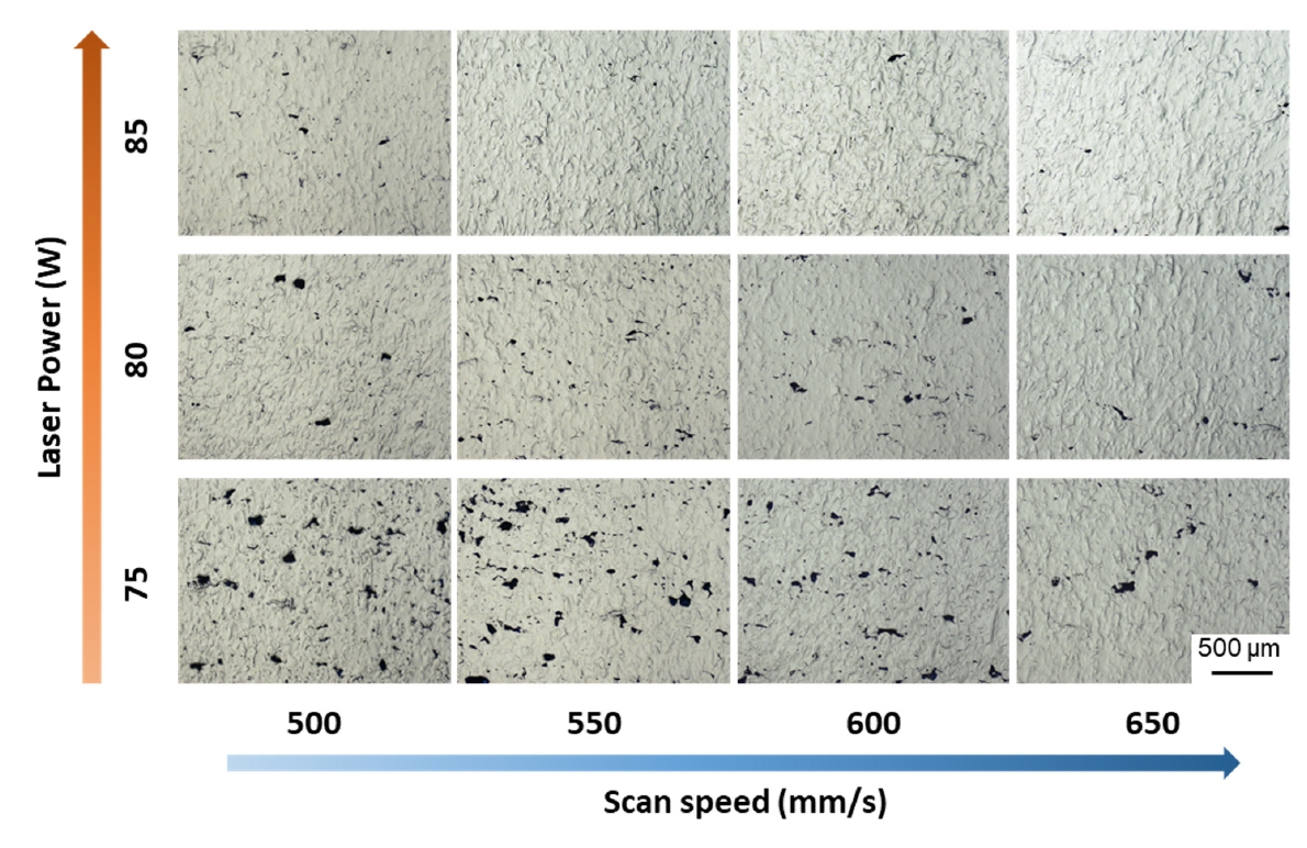
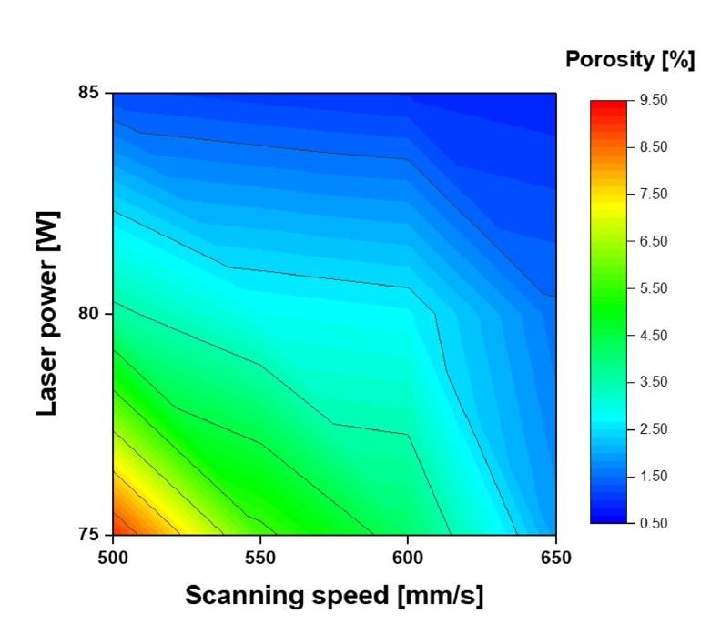

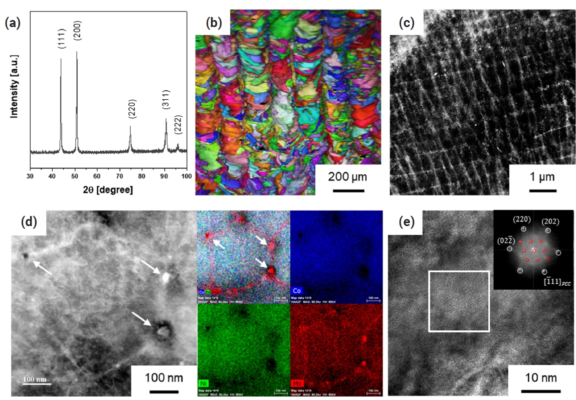

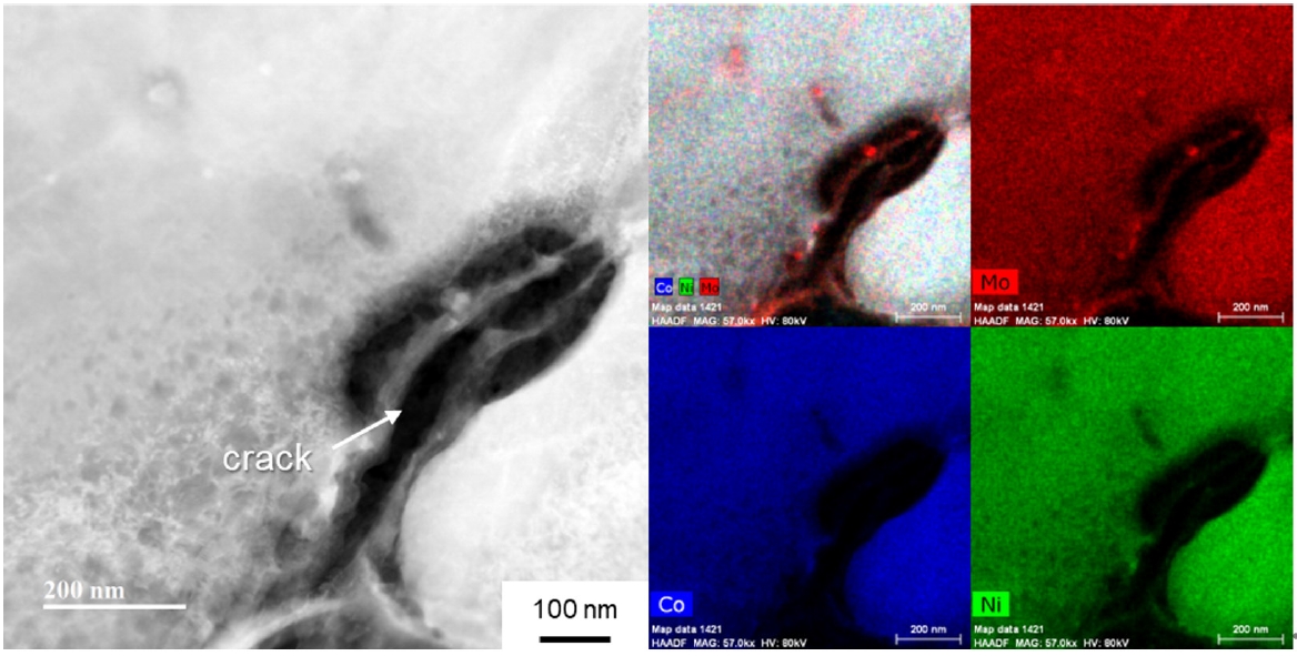


Fig. 1.
Fig. 2.
Fig. 3.
Fig. 4.
Fig. 5.
Fig. 6.
Fig. 7.
TOP
