
Articles
- Page Path
- HOME > J Powder Mater > Volume 33(2); 2026 > Article
-
Research Article
- Ultrasonic Nanocrystal Surface Modification of 3D Interconnected Heterostructured Complex Concentrated Alloys Produced by Liquid Metal Dealloying: Microstructural Evolution and Wear Behavior
- Jumi Choi1,2, Yeji Kim1, Munsu Choi1,3, Jae Hyuk Lee1, Dong Jun Lee4, Auezhan Amanov5, Soo-Hyun Joo1,*, Hyoung Seop Kim2,6,7,8
-
Journal of Powder Materials 2026;33(2):91-103.
DOI: https://doi.org/10.4150/jpm.2026.00045
Published online: April 30, 2026
1Department of Materials Science and Engineering, Dankook University, Cheonan 31116, Republic of Korea
2Graduate Institute of Ferrous & Eco Materials Technology, Pohang University of Science and Technology (POSTECH), Pohang 37673, Republic of Korea
3Extreme Materials Research Institute, Korea Institute of Materials Science, Changwon 51508, Republic of Korea
4Commercialization Research Division, Korea Institute of Materials Science (KIMS), Changwon 51508, Republic of Korea
5Faculty of Engineering and Natural Sciences, Tampere University, PO Box 589, Tampere, FIN-33014, Finland
6Department of Materials Science and Engineering, Pohang University of Science and Technology (POSTECH), Pohang 37673, Republic of Korea
7Center for Heterogenic Metal Additive Manufacturing, Pohang University of Science and Technology (POSTECH), Pohang 37673, Republic of Korea
8Advanced Institute for Materials Research (WPI-AIMR), Tohoku University, Sendai, 980-8577, Japan
- *Corresponding authors: Soo-Hyun Joo Email: jjsh83@dankook.ac.kr
© The Korean Powder Metallurgy & Materials Institute
This is an Open Access article distributed under the terms of the Creative Commons Attribution Non-Commercial License (http://creativecommons.org/licenses/by-nc/4.0/) which permits unrestricted non-commercial use, distribution, and reproduction in any medium, provided the original work is properly cited.
- 1,033 Views
- 21 Download
Abstract
- This study investigates the effects of ultrasonic nanocrystal surface modification (UNSM) on the microstructural evolution and tribological performance of a three-dimensional interconnected heterostructured compositionally complex alloy fabricated by liquid metal dealloying (LMD). The as-LMD microstructure comprises an interconnected Cu-rich phase and a CoCrFe-rich ligament phase. Electron backscatter diffraction reveals pronounced severe plastic deformation near the surface after UNSM, characterized by subgrain formation and increased intragranular misorientation. The kernel average misorientation distribution reveals a pronounced depth-dependent deformation gradient, with dislocations preferentially accumulating at the interphase boundaries. Vickers hardness increases from approximately 100–120 HV in the as-LMD condition to greater than 270 HV at the surface after UNSM, and the hardening effect remains detectable to a depth of approximately 500 μm. Compressive residual stresses are concentrated within the surface-adjacent ~50 μm. The solid ligament phase exhibits higher compressive residual stress than the Cu-rich phase, reflecting phase-dependent deformation accommodation and stress partitioning. Reciprocating wear tests show a narrower wear track, a markedly reduced wear depth, and a lower and more stable friction coefficient after UNSM. Microscopy shows oxide-layer cracking and delamination in the as-LMD condition, whereas the UNSM-treated surface exhibits minor abrasive wear of the tribo-film without delamination.
- Complex concentrated alloys (CCAs), composed of multiple principal elements at relatively high concentrations, differ fundamentally from conventional alloys that are typically based on one or two principal elements [1, 2]. In this context, high-entropy alloys (HEAs) are widely regarded as a subset of CCAs, typically defined by near-equiatomic compositions and high configurational entropy [3]. Such compositional complexity yields high configurational entropy and significant chemical disorder, which can favor the formation and stability of solid-solution phases over ordered intermetallic compounds, depending on composition and processing conditions. Recently, the concept of CCAs (including HEAs) has expanded from single-phase solid solutions to alloys with intentionally tailored heterogeneous microstructures [4-6], enabling enhanced properties through compositional and microstructural design enabled by the multi-principal-element framework. Consequently, CCAs have demonstrated attractive combinations of strength and ductility, corrosion resistance, and wear performance, highlighting their potential as next-generation structural materials for a wide range of applications [7-10].
- Among various CCAs, the equiatomic CoCrFeMnNi alloy—commonly referred to as the Cantor alloy—with a single face-centered cubic (FCC) structure has been most extensively investigated [11-13]. The Cantor alloy demonstrates excellent mechanical properties, particularly at cryogenic temperatures, owing to deformation-induced nano-twinning and transformation-induced plasticity behavior [14-16]. Nevertheless, property enhancement in such single-phase solid-solution alloys is largely limited to grain-size control. To overcome this limitation, various approaches such as powder metallurgy [17-19], carbon addition for precipitation strengthening [20, 21], additive manufacturing [22-25], and severe plastic deformation [26, 27] have been explored. More recently, Choi et al. reported a 3D interconnected microstructure in CCAs using the Cantor alloy via the liquid metal dealloying (LMD) process [28].
- LMD is an emerging process that employs a molten metal as a dealloying medium to fabricate 3D interconnected structures [29]. Unlike chemical dealloying, which relies on electrochemical potential differences, LMD proceeds through selective dissolution governed by the thermodynamic miscibility between the precursor elements and the metallic melt [30, 31]. In a typical LMD process, one or more precursor elements that are miscible with the melt preferentially dissolve, whereas the remaining immiscible elements undergo interfacial diffusion and reorganize into a 3D interconnected ligament architecture. Although the governing factors in multicomponent alloy systems remain complex, it has been reported that immersing the Cantor alloy in molten Cu yields a 3D bicontinuous microstructure consisting of CoCrFe-rich ligaments and a Cu-rich phase [28, 32]. This architecture offers a favorable combination of high electrical conductivity from the Cu-rich phase and mechanical strength from the CoCrFe-rich ligaments, thereby mitigating the conventional strength–conductivity trade-off. However, because LMD is performed at elevated temperatures and forms a soft Cu-rich phase, the resulting materials often exhibit limited mechanical strengthening compared with wrought alloys.
- Ultrasonic nanocrystal surface modification (UNSM) is a surface treatment technique that induces severe plastic deformation through a combination of static and high-frequency dynamic impacts, generating deep subsurface plastic deformation [33-36]. The process refines surface grains to the nanometer scale and introduces a high density of dislocations and compressive residual stresses, which enhance tensile strength, wear resistance, fatigue life, and stress corrosion cracking resistance. Moreover, owing to its high efficiency and cost-effectiveness, UNSM has been recognized as one of the most advanced surface severe plastic deformation techniques [37]. In addition, the UNSM process generates a gradient microstructure in which ultrafine surface grains coexist with relatively coarse interior grains. The strain incompatibility across these regions promotes the formation of geometrically necessary dislocations (GNDs), leading to hetero-deformation induced (HDI) strengthening [38, 39].
- In this context, we propose an integrated strategy that combines UNSM with LMD to mitigate the limited strengthening of LMD-derived dual-matrix architectures associated with the soft Cu-rich phase. UNSM is applied to the LMD-processed layer to introduce controlled severe plastic deformation while retaining the 3D interconnected morphology. This integration enables a surface-to-interior strain-gradient 3D interconnected heterostructured architecture in dual-matrix CCAs, and the resulting microstructure–property relationships are systematically elucidated. The effectiveness of the integrated LMD–UNSM route is quantitatively assessed in terms of hardness and wear resistance.
1. Introduction
- 2.1. Precursor preparation and LMD process
- The Co20Cr20Fe20Mn20Ni20 (at%) Cantor alloy ingot was fabricated by vacuum induction melting under an argon atmosphere. High-purity elemental Co, Cr, Fe, Mn, and Ni (99.99 at%) were used as raw materials, and the melt was cast into a plate form by the tilt-casting method. The as-cast ingot was homogenized at 1100 ℃ for 6 h in a tube furnace under a flowing Ar atmosphere, followed by water quenching. The homogenized ingot was subsequently cold-rolled from an initial thickness of 7 mm to a final thickness of 1.5 mm, corresponding to a total thickness reduction of 77%.
- The cold-rolled plates were cut into specimens with dimensions of 40 mm × 10 mm × 1.5 mm and annealed at 1050 ℃ for 12 h under an Ar atmosphere to achieve recrystallization. Prior to the LMD process, the prepared precursor alloys were mechanically polished with SiC papers up to 1200 grit to remove surface contaminants. A hole with a diameter of 1.0 mm was drilled into each specimen to suspend it from a 99.95% pure W wire during the LMD process. The W wire was selected because it is chemically inert to molten Cu.
- The LMD process was carried out in a purified Ar-filled chamber containing 427.4 g of molten Cu (99.9 at%) at 1095 ℃ for 5 min, using an induction heating system. After dealloying, the specimens were extracted from the melt and cooled in the purified Ar atmosphere. The specimen subjected to LMD for 5 min was designated as the As-LMD sample.
- 2.2. UNSM process
- Prior to UNSM treatment, the specimen surfaces were ultrasonically cleaned in ethanol and deionized water for 10 min each to remove surface contaminants. The UNSM process was conducted under the following conditions: the vibration frequency was fixed at 20 kHz, and the amplitude of the ultrasonic horn was set to 30 µm. A static load of 30 N was applied during processing, while the linear travel speed of the specimen was maintained at 2000 mm/min. The UNSM tool was traversed in a bidirectional raster pattern, with alternating scan directions between adjacent passes. The interval between successive impacts was 0.07 mm, and a WC (tungsten carbide) ball tip with a diameter of 2.38 mm was used. The specimen subjected to UNSM was designated as the UNSM-treated sample.
- 2.3. Mechanical and microstructural characterization
- Mechanical properties were evaluated by Vickers hardness testing. Each specimen was mechanically polished with SiC papers up to 4000 grit and measured using a Mitutoyo HM200 micro-Vickers hardness tester under a load of 0.5 kgf and a dwell time of 10 s. Hardness profiles were acquired on cross sections, and the mean hardness values were calculated from at least three indents.
- Wear tests were performed using a linear reciprocating wear-testing machine along the longitudinal direction, parallel to the long scan direction of the bidirectional raster scanning path employed during UNSM. A Si3N4 ball (diameter: 6.0 mm) was employed as the counter body owing to its high hardness and chemical inertness, which minimize counterface wear and provide reproducible contact conditions. The one-way sliding distance between the reversal points was set to 6 mm. The applied load and reciprocating frequency were set to 2.5 N and 1 Hz, respectively, and the total test duration was 2 h. At least two repeated wear tests were performed under each condition. Before testing, the initial mass of each specimen was measured using a high-precision electronic balance with a resolution of 0.1 mg. After testing, the specimens were ultrasonically cleaned in anhydrous ethanol for 5 min, dried, and weighed again. The wear loss was determined from the difference between pre- and post-test masses. The wear-track depth was quantitatively evaluated using a 3D surface profiler (Zygo Corporation, Zygo Zegage PRO).
- 2.4. Microstructural analysis
- All specimens for microstructural characterization were mechanically ground using 4000-grit SiC paper and then sequentially polished with diamond suspensions of 9, 3, and 1 µm particle size. The polished surfaces were subsequently treated by ion-beam milling (LEICA, EM TIC 3X). Energy-dispersive X-ray spectroscopy (EDS) and electron backscatter diffraction (EBSD, TSL Hikari Super) analyses were performed using a field-emission scanning electron microscope (FE-SEM, ZEISS, SIGMA500). EBSD maps were acquired using a step size of 0.15 μm. Data points with a confidence index (CI), calculated from the Kikuchi patterns, below 0.09 were excluded from the analysis. The EBSD data were processed and interpreted using TSL/OIM software. X-ray diffraction (XRD) was performed on a Rigaku MiniFlex diffractometer with Cu Kα1 radiation (λ = 1.5406 Å) over the 2θ range of 40–100°, with a scan rate of 4° min−1 and a step size of 0.02°. Residual stresses were measured by XRD-based stress analysis (Xstress3000 G3, Stresstech, Finland) with an Mn X-ray tube. Measurements involved determining d-spacing variations as a function of sin2Ψ (Psi angles from -45° to +45°). The precise peak positions (2θ) were extracted by fitting the measured diffraction curves and identifying the center of symmetry of the full width at half maximum. The residual stresses were then calculated from the slope of the 2θ vs. sin2Ψ plot in accordance with the sin2Ψ method (ASTM E915). Prior to measurement, a thin surface layer was removed by electrochemical polishing (20 V, 30 s) to minimize the influence of surface oxidation, roughness, and contamination.
2. Materials and methods
- 3.1. 3D interconnected heterostructure formed by LMD
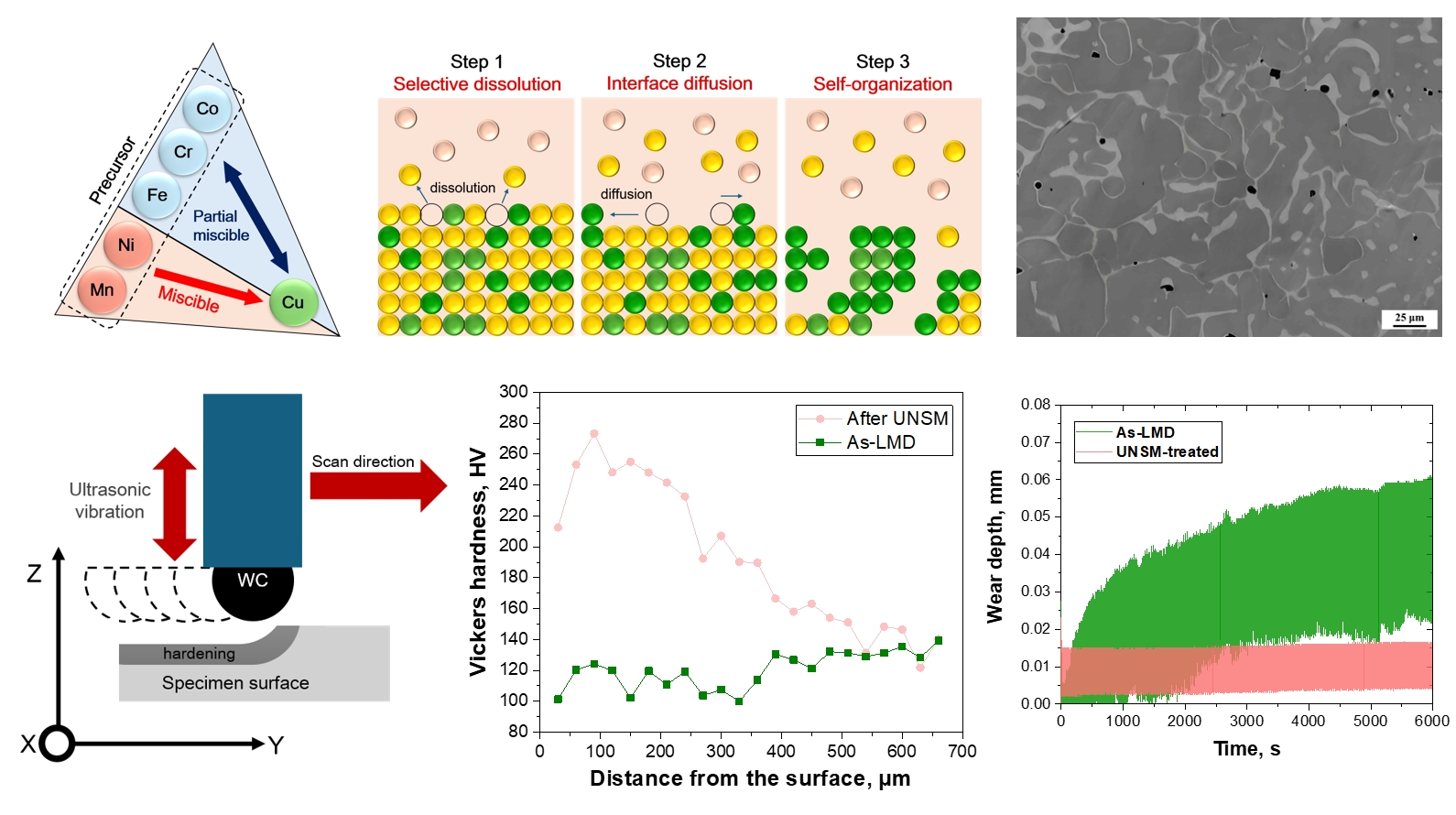
- Fig. 1a–c schematically illustrate the principal steps of a typical LMD process, including selective dissolution at the melt–precursor interface and the subsequent self-organization of the remaining elements into a 3D interconnected architecture. Consider an A–B precursor alloy immersed in a C melt, where element B is miscible with C (often associated with a negative mixing enthalpy), whereas element A is immiscible with C (Fig. 1a). Under this condition, B atoms undergo preferential dissolution into the C melt. In parallel, A atoms left at the melt–precursor interface become energetically unstable due to broken coordination and therefore diffuse along the interface to form more stable bonding configurations (Fig. 1b). As dissolution proceeds, the remaining A atoms progressively reconnect, producing a disordered 3D interconnected ligament network via self-organization. At the same time, the C melt infiltrates the inter-ligament space to form bicontinuous melt channels. Upon withdrawing the specimen from the melt, the infiltrated C channels solidify during cooling. This yields a unique composite in which the A-phase ligament network and the solidified C phase are interlocked in 3D.
- Based on this principle, various LMD systems have been reported, including (Fe)Ni–Mg [40], (FeCr)Ni–Mg [41-43], (FeCo)Ni–Mg [44], (Ti)Cu–Mg [45-47], (C)Mn–Bi [48], (Si)Mg–Bi [49], (Nb)Ni–Mg [50], and (Ta)Ti–Cu [51], among others. Here, the element in parentheses denotes the immiscible element, and the element to the right of the dash denotes the metallic melt. These systems commonly produce a 3D interconnected architecture, with ligament sizes spanning from the sub-nanometer regime to a few micrometers.
- More recently, LMD studies have advanced beyond these simplified systems by tuning the compositions of both the precursor and the melt to control dissolution and morphology [28, 32, 52, 53]. This approach has been extended to multicomponent engineering alloys such as stainless steels, as well as CCAs, enabling 3D interconnected structures while maintaining the composition-governed performance characteristics. For example, T. Wada et al. reported that thermodynamic calculations can be used to regulate the dissolution of miscible elements into the melt [53]. In addition, M. Choi et al. immersed a CoCrFeMnNi CCA precursor in a Cu-alloy melt and exploited differences in solubility and reaction kinetics among the constituent elements. This strategy produced a 3D interconnected CCA composite with dual FCC matrices, thereby enhancing hardness and electrical conductivity simultaneously [28]. Although Co, Cr, Fe, Mn, and Ni are all soluble in Cu, Mn and Ni exhibit higher solubility and faster dissolution kinetics than Co, Cr, and Fe. This kinetic disparity facilitates the development of the 3D interconnected morphology (Fig. 1c).
- In this study, consistent with the previous work [28], a CoCrFeMnNi CCA precursor was immersed in a Cu-alloy melt at 1095 ℃ for 5 min, forming a 3D interconnected surface layer (Fig. 1d). The reaction-layer thickness was nearly uniform, despite minor local variations. The dealloying depth, defined by the penetration of Cu melt channels, was measured to be approximately 217 μm from the surface. The contrast in the enlarged view of Fig. 1e reflects compositional (Z-contrast) differences in the backscattered electron (BSE) image. ImageJ analysis yielded a ligament size of 20.5 ± 9.3 μm, a melt-channel thickness of 4.8 ± 2.7 μm, and a melt-channel area fraction of 14.5%.
- Fig. 2 presents the EDS elemental maps obtained to examine the compositional distribution within the reaction layer that developed a 3D interconnected structure. The Cu map confirms that the bright region in Fig. 1e corresponds to a Cu-rich phase formed by Cu infiltration into the precursor alloy. In contrast, Cr, Co, and Fe were concentrated in regions with a low Cu signal, forming a CoCrFe-rich solid ligament network. Mn showed an almost uniform distribution, which suggests that Mn preferentially dissolved from the precursor, migrated into the Cu melt channels, diffused toward the precursor surface, and was removed into the Cu melt bath. Ni did not exhibit as pronounced a contrast with Cu as Cr, Co, and Fe, but it was still enriched in the solid ligaments. This trend is attributed to the slower dissolution kinetics of Ni compared with Mn. Overall, the EDS maps clearly demonstrate the successful formation of a 3D interconnected composite consisting of CoCrFe-rich and Cu-rich phases. Quantitative analysis further indicates that the precursor composition of Co20Cr20Fe20Mn20Ni20 evolved to Co21.2Cr20.8Fe20.8Mn5.5Ni15.0Cu16.7 at.% within the reaction layer after LMD for 5 min, thereby forming a 3D interconnected heterostructured CCA (average of three area analyses, with a maximum deviation of 1.9 at.%).
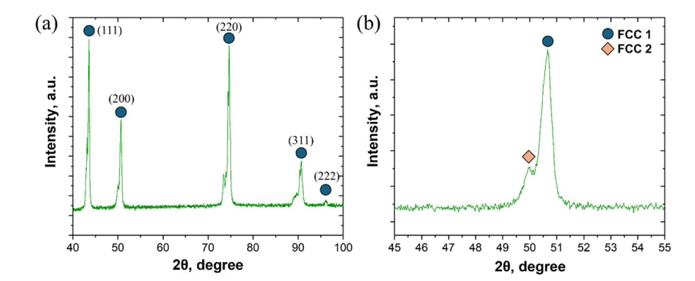
- Fig. 3 shows the XRD pattern of the as-LMD specimen. Distinct diffraction peaks were observed at 2θ values of 43.54°, 50.66°, 74.66°, 90.74°, and 96.12°. These peaks indicate that the heterogeneous 3D interconnected CCA produced by LMD is primarily based on an FCC crystal structure. Fig. 3b presents a magnified view of the FCC (111) peak and clearly shows that the as-LMD specimen exhibits a dual-FCC structure rather than a single FCC phase. Similar peak splitting was also observed for the other reflections. The presence of two discernible peaks (FCC1 and FCC2) suggests the coexistence of two FCC phases with different lattice parameters. This interpretation is consistent with the FE-SEM and EDS results, indicating that the LMD process produces a heterostructured material comprising a Cu-rich FCC phase and a CoCrFe-rich FCC phase.
- 3.2. Microstructural evolution after UNSM
- Fig. 4 shows cross-sectional FE-SEM images acquired from the surface into the depth direction after applying UNSM to the LMD specimen. The schematic in Fig. 4a illustrates the formation of a near-surface deformed layer during the UNSM process. The low-magnification image in Fig. 4b indicates that UNSM does not introduce an obvious macroscopic change in the dealloyed reaction layer. Quantitative analysis confirms that the characteristic morphology and phase distribution remain nearly unchanged before and after UNSM, with an average ligament size of 23.7 μm, a Cu-rich phase size of 5.1 μm, and a Cu-rich phase fraction of 18.6%. No pronounced macroscopic modification is observed even in the near-surface region that is directly contacted by the WC ball.
- In contrast, higher-magnification images reveal deformation-related features within both the CoCrFe-rich ligaments and the Cu-rich phase. Fig. 4c, taken from the mid-thickness of the dealloyed layer, demonstrates that a substantial population of deformation-induced defects is present even at locations more than 100 μm below the surface. In the BSE image, the observed banded contrast reflects electron channeling contrast (ECC) arising from deformation-induced orientation gradients and defect substructures. Importantly, the morphology of these bands depends on the slip character, which is strongly governed by the stacking fault energy (SFE) in FCC materials. In relatively higher-SFE FCC metals such as pure Cu, frequent cross-slip promotes wavy slip and dynamic recovery, often producing diffuse contrast associated with dislocation cells or subgrains rather than sharply defined planar bands [54, 55]. In contrast, lower-SFE FCC alloys exhibit stronger dislocation dissociation, which suppresses cross-slip and favors planar slip, thereby enhancing strain localization on specific {111} planes and generating sharper band contrast [56]. In the present heterostructure, the Cu-rich phase exhibited comparatively wavy, cell/subgrain-related deformation contrast, whereas the CoCrFe-rich ligaments showed sharper, planar slip–dominated band contrast. This phase-dependent contrast difference, reflecting a distinct transition in slip character, suggests a lower effective SFE and stronger suppression of cross-slip in the CoCrFe-rich ligaments relative to the Cu-rich phase. Although specific SFE values for the exact compositions formed via LMD-induced redistribution are not available in the literature, the observed planar slip is highly characteristic of low-SFE FCC systems, such as CoCrFe-based complex concentrated alloys, while the wavy slip in the Cu-rich phase aligns with the higher SFE typically reported for Cu-based systems. The intersecting band families observed within individual ligaments are more appropriately interpreted as signatures of localized planar slip on multiple active slip systems.
- Fig. 4d presents a higher-magnification image near the LMD reaction layer. Although the degree of deformation is less pronounced than that in the mid-thickness region, deformation-related contrast remains clearly visible. Notably, deformation features are also observed in the unreacted equiaxed CoCrFeMnNi precursor grains adjacent to the reaction layer. In contrast, at a depth of approximately 100 μm below the reaction layer, the equiaxed microstructure characteristic of the CoCrFeMnNi precursor is largely retained and less deformed (Fig. 4e). These observations indicate that UNSM can produce a gradient structure in the LMD-derived 3D interconnected heterostructured layered CCA, where the extent of deformation decreases progressively from the surface toward the interior.
- Fig. 5 presents the EBSD results for the near-surface layer after UNSM. During UNSM, plastic deformation is induced by repetitive impacts of a ball subjected to high-frequency vibration. The inverse pole figure (IPF) map reveals the formation of numerous subgrains within the surface grains after UNSM (Fig. 5a). The kernel average misorientation (KAM) map shows markedly elevated local misorientation within the surface-adjacent region (Fig. 5b), suggesting the accumulation of a high dislocation density, particularly GNDs. The KAM intensity diminishes with depth, reflecting a progressively reduced plastic strain gradient.
- In addition, UNSM induces severe plastic deformation in the near-surface region, leading to the formation of new grain boundaries (Fig. 5c). The accumulated dislocations progressively rearrange into dislocation walls and subgrain boundaries, which increases the fraction of low-angle grain boundaries. With continued deformation, progressive subgrain rotation increases the local misorientation, thereby converting low-angle boundaries into high-angle boundaries [57]. This microstructural evolution provides a mechanistic basis for grain refinement toward an ultrafine-grained or nanocrystalline surface layer in the 3D interconnected heterostructured CCA investigated in this study.
- When the SFE is low, stacking faults and deformation twinning can further assist microstructural subdivision and thereby accelerate grain refinement [58]. Although twinning boundaries may not be fully resolved in the EBSD maps, nanotwinning has been reported in CoCrFeMnNi during room-temperature tensile deformation [59]. In the present study, EBSD evidence further supports twinning activity. Specifically, Σ3 twin boundaries are observed in Fig. 5c. In addition, along the white arrow in Fig. 5a, a boundary with a misorientation of ~60° is identified (Fig. 5d). This misorientation is characteristic of an FCC Σ3 twin boundary, suggesting that deformation twinning was activated during UNSM in the CoCrFe-rich ligaments. UNSM is characterized by very high strain rates and a complex stress state generated by high-frequency impacts [37]. Under such conditions, dynamic recovery and cross-slip are increasingly constrained, particularly in low-SFE FCC alloys, and deformation twinning can emerge as a competitive strain-accommodation mechanism in addition to dislocation slip [60].
- Notably, higher KAM values are observed near the phase boundaries and within the relatively softer Cu-rich phase in the dual-FCC heterostructure, indicated by white dashed circles. This behavior can be interpreted in terms of heterogeneous deformation arising from differences in intrinsic properties between the two phases. The resulting strain incompatibility across the phase boundaries can enhance HDI hardening and promote additional GND accumulation in the vicinity of the interfaces [61, 62].
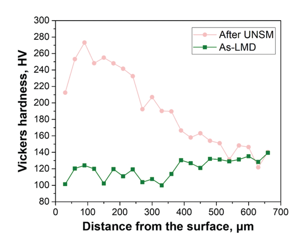
- Fig. 6 shows the Vickers hardness profiles measured from the surface into the depth for the as-LMD and UNSM-treated specimens. For the as-LMD specimen, the Cu-reacted layer exhibits hardness values of approximately 100–120 HV. These values are slightly lower than those of the unreacted CoCrFeMnNi precursor (about 120 HV), although the difference is not pronounced. After UNSM, the near-surface hardness increases markedly to above 270 HV, which corresponds to an approximately 2.25-fold increase relative to the as-LMD level. The hardness gradually decreases with increasing distance from the surface without an abrupt drop, and it remains above 200 HV through the LMD reaction layer. Notably, the UNSM-induced hardening is detectable to a depth of up to ~500 μm. This depth is within the range reported for UNSM conducted under similar loading conditions (around 30 N), where the affected depth spans roughly 300–1000 μm depending on the material [63, 64]. Therefore, the present results indicate that the affected depth (~500 μm) is substantially larger than the LMD reaction-layer thickness (~217 μm), suggesting that UNSM can introduce deformation-induced dislocation accumulation not only within the dealloyed layer but also into the underlying undealloyed precursor region.
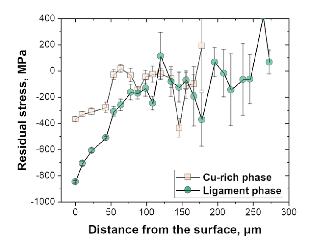
- UNSM is an effective surface modification technique that enhances wear resistance and fatigue performance by introducing a deformation gradient and residual compressive stress in the near-surface region. Fig. 7 shows the residual stress distributions of the Cu-rich phase and the CoCrFe-rich phase as a function of distance from the surface after UNSM. To ensure accurate peak separation for residual stress analysis, we employed a Mn-target X-ray source, which provides a longer wavelength compared to Cu-target, effectively increasing the peak resolution. This allowed for the clear separation and fitting of the (311) diffraction peaks for both the Cu-rich and CoCrFe-rich phases. Regarding the elastic moduli, since specific reference data for the exact compositions of the dealloyed phases are unavailable in the literature, values for CoCrFeMnNi (200 GPa [65]) and Cu alloys (120 GPa [66]) were adopted as reasonable approximations. Although minor discrepancies may arise from compositional variations, these values are considered reliable benchmarks for a comparative analysis of the relative residual stress states between the two phases. Both phases exhibit pronounced compressive residual stresses near the surface, which persist to a depth of approximately 50 μm. In particular, the maximum compressive residual stresses at the surface reach ~370 MPa for the Cu-rich phase and ~850 MPa for the solid-ligament phase. At a depth of 50 μm, the compressive residual stresses decrease to ~280 MPa and ~510 MPa, respectively. Notably, the compressive residual stress decreases rapidly beyond 50 μm and approaches nearly zero at ~150 μm. The steep reduction in hardness at depths exceeding 200 μm in Fig. 6 presumably reflects the point where the influence of both compressive residual stress and UNSM-induced plastic strain effectively disappears. The large error bars beyond ~150 μm are likely attributable to the coarse grain size in this region, which reduces the statistical representativeness of the measurements.
- The larger compressive residual stress in the solid-ligament phase can be attributed to the difference in mechanical properties between the two phases. In general, the CoCrFe-rich ligament is stiffer and harder than the Cu-rich phase, and thus it can sustain a higher stress level (or store a larger elastic strain energy) under UNSM loading. Consequently, upon unloading after impact, the ligament phase can retain a larger portion of the elastic strain energy in the form of residual compressive stress. In contrast, the softer Cu-rich phase is more susceptible to plastic deformation and may undergo partial stress relaxation during deformation, resulting in a smaller magnitude of residual compressive stress. In addition, strain incompatibility in this heterogeneous architecture can promote stress partitioning near the phase boundaries, such that the mechanically stronger ligament phase carries a greater fraction of the compressive residual stress.
- 3.3. Tribological performance
- Fig. 8 presents FE-SEM images of the wear tracks after the linear reciprocating wear test. Compared with the as-LMD specimen, the UNSM-treated specimen exhibits a markedly narrower wear track (Fig. 8a and b), indicating an improved wear resistance after UNSM. Notably, the worn-surface morphology and the associated wear mechanisms differ markedly between the two specimens. While the as-LMD worn surface shows a mixture of bright and dark regions, the UNSM-treated specimen displays a generally darker worn area relative to the surrounding region. The magnified images further clarify the dominant wear mechanisms (Fig. 8c and d). For the as-LMD specimen, an oxide layer formed during sliding undergoes cracking under the tangential stress generated during reciprocating motion. The cracks propagate preferentially perpendicular to the sliding direction, which ultimately promotes delamination of the surface layer [67].
- In contrast, the UNSM-treated specimen primarily shows features associated with abrasive wear, and no apparent delamination is observed. This behavior can be attributed to the increased hardness and the compressive residual stress introduced by UNSM, which enhance resistance to material removal and suppress cracking and spallation of the tribo-oxide layer. Consequently, the wear process in the UNSM-treated specimen is effectively confined to a milder abrasive-wear regime.
- Fig. 9a and b show the wear depth and friction coefficient obtained from the linear reciprocating wear test. The large fluctuations in the signals would be attributed to the periodic reversal of the sliding direction inherent to reciprocating motion, which alters the contact conditions. Consistent with these trends, the wear loss decreased from 1.9 ± 0.2 mg for the as-LMD specimen to 0.7 ± 0.2 mg for the UNSM-treated specimen. Accordingly, the as-LMD specimen exhibits a substantially larger wear depth than the UNSM-treated specimen, which is consistent with the transverse wear-depth profiles measured using a laser profiler (Fig. 9c and d). The as-LMD specimen shows a wear depth of ~46 μm at the center of the wear track, which is comparable to the final wear-depth value recorded by the tribometer. In contrast, the UNSM-treated specimen exhibits a markedly reduced wear depth of approximately 1.8 μm, which is slightly higher than the initial surface roughness level (up to 0.8 μm). Notably, the wear depth for the UNSM-treated specimen increases during the initial stage and then shows little further increase with time (Fig. 9a). This behavior could suggest a transition from a running-in stage to a steady-state regime, possibly associated with the formation of a protective tribo-oxide (tribo-film) that reduces direct material removal. Although direct chemical or structural evidence was not obtained in this study, it is tentatively proposed that the high compressive residual stress introduced by UNSM may further stabilize this potential protective layer by suppressing cracking and spallation of the tribo-film.
- The friction coefficient results in Fig. 9b highlight the distinct tribological responses. The as-LMD specimen exhibits pronounced fluctuations with a higher peak friction coefficient during reciprocating sliding, indicating an unstable wear process. By contrast, the UNSM-treated specimen maintains a lower and more stable friction coefficient, reflecting improved wear resistance and a more stable tribological behavior.
3. Results and discussion
- The present work demonstrates that UNSM is an effective post-treatment for a 3D interconnected heterostructured CCA fabricated by LMD, in which a Cu-rich phase and a CoCrFe-rich solid-ligament phase form an interconnected architecture.
- 1) Electron backscatter diffraction indicates that UNSM induces pronounced near-surface plastic deformation, evidenced by extensive subgrain formation and increased intragranular misorientation. The KAM results demonstrate a clear deformation gradient with distance from the surface. Consistent with this evolution, the Vickers hardness increases from approximately 100–120 HV in the as-LMD condition to greater than 270 HV at the surface after UNSM, corresponding to an approximately 2.25-fold increase. The hardening effect remains detectable to a depth of approximately 500 μm.
- 2) Depth-resolved residual stress measurements reveal substantial compressive residual stresses within the top approximately 50 μm, followed by a rapid decrease toward nearly zero by approximately 150 μm. The CoCrFe-rich solid-ligament phase exhibits higher compressive residual stress than the Cu-rich phase, which is attributed to phase-dependent deformation accommodation and stress partitioning across the heterogeneous architecture.
- 3) These microstructural and stress-state modifications lead to a marked improvement in reciprocating wear performance. The UNSM-treated specimen exhibits a narrower wear track, a substantially reduced wear depth (maximum approximately 1.8 μm), and a lower and more stable friction coefficient than the as-LMD specimen (center wear depth approximately 46 μm). Microscopy reveals oxide-layer cracking and delamination in the as-LMD condition, whereas such damage is markedly reduced after UNSM, likely because a tribo-film acts as a protective barrier and suppresses severe material removal during sliding.
4. Conclusions
-
Funding
This work was supported by the National Research Foundation of Korea (NRF) grants funded by the Korea government (MSIT) (RS-2025-00556562). This work was supported by the Nano & Material Technology Development Program through the National Research Foundation of Korea (NRF) funded by Ministry of Science and ICT (RS-2023-00281246).
-
Conflict of Interest
The authors declare that they have no known competing financial interests or personal relationships that could have appeared to influence the work reported in this paper.
-
Data Availability Statement
Data will be made available on request.
-
Author Information and Contribution
Jumi Choi: Writing – original draft, Visualization, Methodology, Investigation, Formal analysis, Yeji Kim: Visualization, Methodology, Data curation. Munsu Choi: Investigation, Data curation, Jae Hyuk Lee: Resources, Investigation. Dong Jun Lee: Resources, Investigation. Auezhan Amanov: Validation, Investigation. Soo-Hyun Joo: Writing – review & editing, Supervision, Project administration, Conceptualization, Funding acquisition. Hyoung Seop Kim: Supervision, Funding acquisition.
-
Acknowledgments
None.
Article information


- 1. I. J. Beyerlein, P. Cao and T. M. Pollock: MRS Bulletin, 48 (2023) 746.ArticlePDF
- 2. H. S. Oh, S. J. Kim, K. Odbadrakh, W. H. Ryu, K. N. Yoon, S. Mu, F. Körmann, Y. Ikeda, C. C. Tasan, D. Raabe, T. Egami and E. S. Park: Nat. Commun., 10 (2019) 2090.Article
- 3. J. Pradeep Kumar, S. Manova, V. Uthaisangsuk, L. G. Asirvatham and S. Wongwises: Met. Mater. Int., (2025).
- 4. X. H. Du, W. P. Li, H. T. Chang, T. Yang, G. S. Duan, B. L. Wu, J. C. Huang, F. R. Chen, C. T. Liu, W. S. Chuang, Y. Lu, M. L. Sui and E. W. Huang: Nat. Commun., 11 (2020) 2390.Article
- 5. S. K. Guo, Z. L. Ma, G. H. Xia, X. Y. Li, Z. Q. Xu, W. Z. Li, X. Y. Jin and X. W. Cheng: Acta Mater., 263 (2024) 119492.Article
- 6. Y. Wang, X. Ma, F. Guo, Z. Zhao, C. Huang, Y. Zhu and Y. Wei: Mater. Des., 225 (2023) 111593.Article
- 7. Y. Geng, W. Chen, H. Tan, J. Cheng, S. Zhu, J. Yang and W. Liu: Research, 6 (2023) 0160.Article
- 8. B. Gwalani, S. Gorsse, D. Choudhuri, M. Styles, Y. Zheng, R. S. Mishra and R. Banerjee: Acta Mater., 153 (2018) 169.Article
- 9. Y. Shi, B. Yang and P. K. Liaw: Metals, 7 (2017) 43.Article
- 10. D. K. Yadav, Y. Shadangi, S. D. Yadav and S. Sinha: Mater.Today Commun., 35 (2023) 105521.Article
- 11. W.-M. Choi, Y. H. Jo, S. S. Sohn, S. Lee and B.-J. Lee: npj Comput. Mater., 4 (2018) 1.Article
- 12. D. Ma, B. Grabowski, F. Körmann, J. Neugebauerand and D. Raabe: Acta Mater., 100 (2015) 90.Article
- 13. F. Otto, A. Dlouhý, C. Somsen, H. Bei, G. Eggeler and E. P. George: Acta Mater., 61 (2013) 5743.Article
- 14. R. E. Kim, J. Choi, H. H. Lee, B. W. Koo, S. W. Lee, S. Son, H. Ha, D.W. Lee, D.-W. Suh and H. S. Kim: Mater. Res. Lett., 14 (2026) 96.Article
- 15. M. Klimova, D. Shaysultanov, A. Semenyuk, S. Zherebtsov, G. Salishchev and N. Stepanov: J. Alloys Compd., 849 (2020) 156633.Article
- 16. Z. Li, C. C. Tasan, H. Springer, B. Gault and D. Raabe: Sci. Rep., 7 (2017) 40704.Article
- 17. S. H. Joo, H. Kato, M. J. Jang, J. Moon, E. B. Kim, S. J. Hong and H. S. Kim: J. Alloys Compd., 698 (2017) 591.Article
- 18. E. S. Kim, J. M. Park, J. S. Lee, J. Choe, S. Y. Ahn, S. G. Jeong, D. W. Lee, S. J. Park and H. S. Kim: J. Powder Mater., 30 (2023) 1.Article
- 19. C. Nagarjuna, S. K. Dewangan, H. Lee, E. Song, K. R. Rao and B. Ahn: J. Powder Mater., 32 (2025) 145.Article
- 20. J. Y. Ko, J. S. Song and S. I. Hong: Korean J. Met. Mater., 56 (2018) 26.Article
- 21. J. Peng, Z. Li, L. Fu, X. Ji, Z. Pang and A. Shan: J. Alloys Compd., 803 (2019) 491.Article
- 22. C. Bulut, F. Yıldız, T. Varol, G. Kaya and T. O. Ergüder: Met. Mater. Int., 30 (2024) 2982.ArticlePDF
- 23. X. Jia, Z. Xu, Y. He, S. Zhou, X. Du, H. Zhang and A. Mao: Met. Mater. Int., 29 (2023) 2895.ArticlePDF
- 24. S. N. Singh and A. B. Deoghare: Met. Mater. Int., 29 (2023) 1563.ArticlePDF
- 25. Z. Xu, H. Zhang, X. Du, Y. He, H. Luo, G. Song, L. Mao, T. Zhou and L. Wang: Corros. Sci., 177 (2020) 108954.Article
- 26. A. Kilmametov, R. Kulagin, A. Mazilkin, S. Seils, T. Boll, M. Heilmaier and H. Hahn: Scr. Mater., 158 (2019) 29.Article
- 27. B. Schuh, F. Mendez-Martin, B. Völker, E.P. George, H. Clemens, R. Pippan and A. Hohenwarter: Acta Mater., 96 (2015) 258.Article
- 28. M. Choi, G. H. Gu, J. Moon, J. W. Bae, H. Kato, S. Z. Han, H. S. Kim, Y. Choi and S.-H. Joo: J. Mater. Res. Technol., 37 (2025) 5672.Article
- 29. T. Wada, K. Yubuta, A. Inoue and H. Kato: Mater. Lett., 65 (2011) 1076.Article
- 30. P.-A. Geslin, I. McCue, B. Gaskey, J. Erlebacher and A. Karma: Nat. Commun., 6 (2015) 8887.Article
- 31. J. E. Jang, S. H. Joo and S. H. Park: Korean J. Met. Mater., 62 (2024) 820.ArticlePDF
- 32. M. Choi, H. Cho, J. H. Lee, A. Takeuchi, H. Kato, H. S. Kim, S.-J. Hong, Y. Choi, S. Z. Han and S. H. Joo: J. Mater. Res. Technol., 41 (2026) 2105.Article
- 33. A. Amanov, I.-S. Cho, D.-E. Kim and Y.-S. Pyun: Surf. Coat. Technol., 207 (2012) 135.Article
- 34. X. J. Cao, Y. S. Pyoun and R. Murakami: Appl. Surf. Sci., 256 (2010) 6297.Article
- 35. R. Liu, S. Yuan, N. Lin, Q. Zeng, Z. Wang and Y. Wu: J. Mater. Res. Technol., 11 (2021) 351.Article
- 36. H.-B. Park, H.-J. Ha, J.-R. Cho and D.-S. Shim: Metals Mater. Int., 31 (2025) 423.ArticlePDF
- 37. A. Kishore, M. John, A. M. Ralls, S. A. Jose, U. B. Kuruveri and P. L. Menezes: Nanomaterials, 12 (2022) 1415.Article
- 38. R. E. Kim, G. M. Karthik, A. Amanov, Y.-U. Heo, S. G. Jeong, G. H. Gu, H. Park, E. S. Kim, D. W. Lee and H. S. Kim: Scr. Mater., 230 (2023) 115422.Article
- 39. J. S. Lee, P. W. Shin, P. Asghari-Rad, A. Amanov, H. S. Kim and J. W. Bae: Mater. Sci. Eng. A, 952 (2026) 149647.Article
- 40. K. Kurabayashi, T. Wada and H. Kato: Scr. Mater., 230 (2023) 115404.Article
- 41. S. V. Ha, G. H. Gu, H. S. Kim and S.-H. Joo: Korean J. Met. Mater., 62 (2024) 673.ArticlePDF
- 42. Y. B. Jeong, T. Wada, S.-H. Joo, J.-M. Park, J. Moon, H. S. Kim, I. V. Okulov, S. H. Park, J. H. Lee, K. B. Kim and H. Kato: Composites, Part B, 225 (2021) 109266.Article
- 43. Y. B. Jeong, T. Wada, J. Seong, G. H. Gu, H. S. Kim, S. H. Joo and H. Kato: Adv. Compos. Hybrid Mater., 8 (2025) 373.Article
- 44. S. H. Joo and H. Kato: J. Alloys Compd., 908 (2022) 164688.Article
- 45. J. E. Jang, B. H. Park, H. J. Youn, S.-H. Joo and S. H. Park: J. Mater. Res. Technol., 41 (2026) 1106.Article
- 46. I. V. Okulov, J. Wilmers, S.-H. Joo, S. Bargmann, H. S. Kim and H. Kato: Scr. Mater., 194 (2021) 113660.Article
- 47. J. Seong, J. E. Jang, H. Kato, S. H. Park and S.-H. Joo: J. Mater. Res. Technol., 39 (2025) 4453.Article
- 48. W.-Y. Park, J. Han, J. Moon, S.-H. Joo, T. Wada, Y. Ichikawa, K. Ogawa, H. S. Kim, M. Chen and H. Kato: Adv. Mater., 36 (2024) 2311792.Article
- 49. T. Wada, T. Ichitsubo, K. Yubuta, H. Segawa, H. Yoshida and H. Kato: Nano Lett., 14 (2014) 4505.Article
- 50. J. W. Kim, M. Tsuda, T. Wada, K. Yubuta, S. G. Kim and H. Kato: Acta Mater., 84 (2015) 497.Article
- 51. I. McCue, B. Gaskey, P.-A. Geslin, A. Karma and J. Erlebacher: Acta Mater., 115 (2016) 10.Article
- 52. J. H. Lee, S. V. Ha, J. Seong, A. Takeuchi, R. Song, H. Kato and S.-H. Joo: J. Mater. Res. Technol., 35 (2025) 5204.Article
- 53. T. Wada, P.-A. Geslin, D. Wei and H. Kato: Commun. Mater., 4 (2023) 43.Article
- 54. M. Asano, M. Yuasa and H. Miyamoto: Mater. Sci. Eng. A, 803 (2021) 140716.Article
- 55. C. S. Patil, S. Chakraborty and S. R. NiezgodaP: Acta Mater., 272 (2024) 119913.Article
- 56. D. T. Pierce, J. A. Jiménez, J. Bentley, D. Raabe and J. E. Wittig: Acta Mater., 100 (2015) 178.Article
- 57. T. Sakai, A. Belyakov, R. Kaibyshev, H. Miura and J. J. Jonas: Prog. Mater Sci., 60 (2014) 130.Article
- 58. Y. B. Wang, X. Z. Liao, Y. H. Zhao, E. J. Lavernia, S. P. Ringer, Z. Horita, T. G. Langdon and Y. T. Zhu: Mater. Sci. Eng. A, 527 (2010) 4959.Article
- 59. S. H. Joo, H. Kato, M. J. Jang, J. Moon, C. W. Tsai, J. W. Yeh and H. S. Kim: Mater. Sci. Eng. A, 689 (2017) 122.Article
- 60. G.T. Gray: Annu. Rev. Mater. Res., 42 (2012) 285.Article
- 61. X. Wu and Y. Zhu: Mater. Res. Lett., 5 (2017) 527.ArticlePDF
- 62. Y. Zhu, K. Ameyama, P. M. Anderson, I. J. Beyerlein, H. Gao, H. S. Kim, E. Lavernia, S. Mathaudhu, H. Mughrabi, R. O. Ritchie, N. Tsuji, X. Zhang and X. Wu: Mater. Res. Lett., 9 (2021) 1.Article
- 63. K. T. Kim and Y. S. Kim: Materials, 12 (2019) 3165.Article
- 64. B. Singh, R. M. Karimbaev, A. K. Sharma, A. Amanov and S. Zafar: Surf. Coat. Technol., 428 (2021) 127893.Article
- 65. G. Laplanche, P. Gadaud, O. Horst, F. Otto, G. Eggeler and E. P. George: J. Alloys Compd., 623 (2015) 348.Article
- 66. V. Subramanya Sarma, K. Sivaprasad, D. Sturm and M. Heilmaier: Mater. Sci. Eng. A, 489 (2008) 253.Article
- 67. F. H. Stott: Tribol. Int., 31 (1998) 61.Article
References
Figure & Data
References
Citations
 ePub Link
 Cite this Article
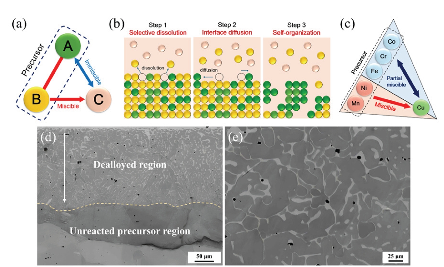
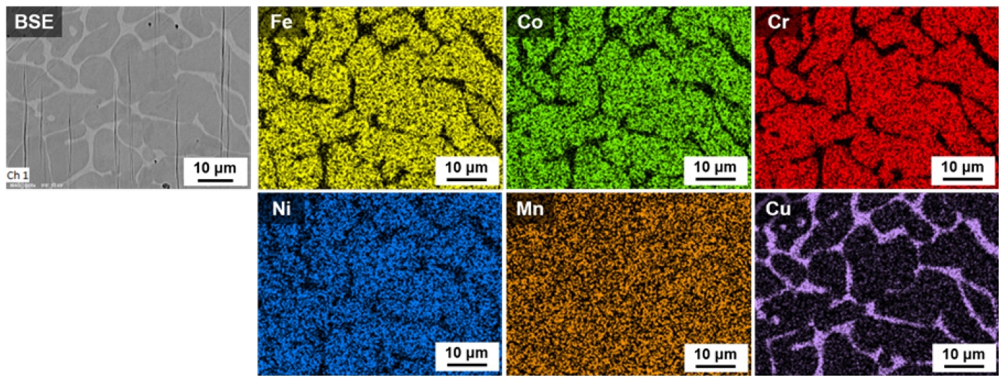

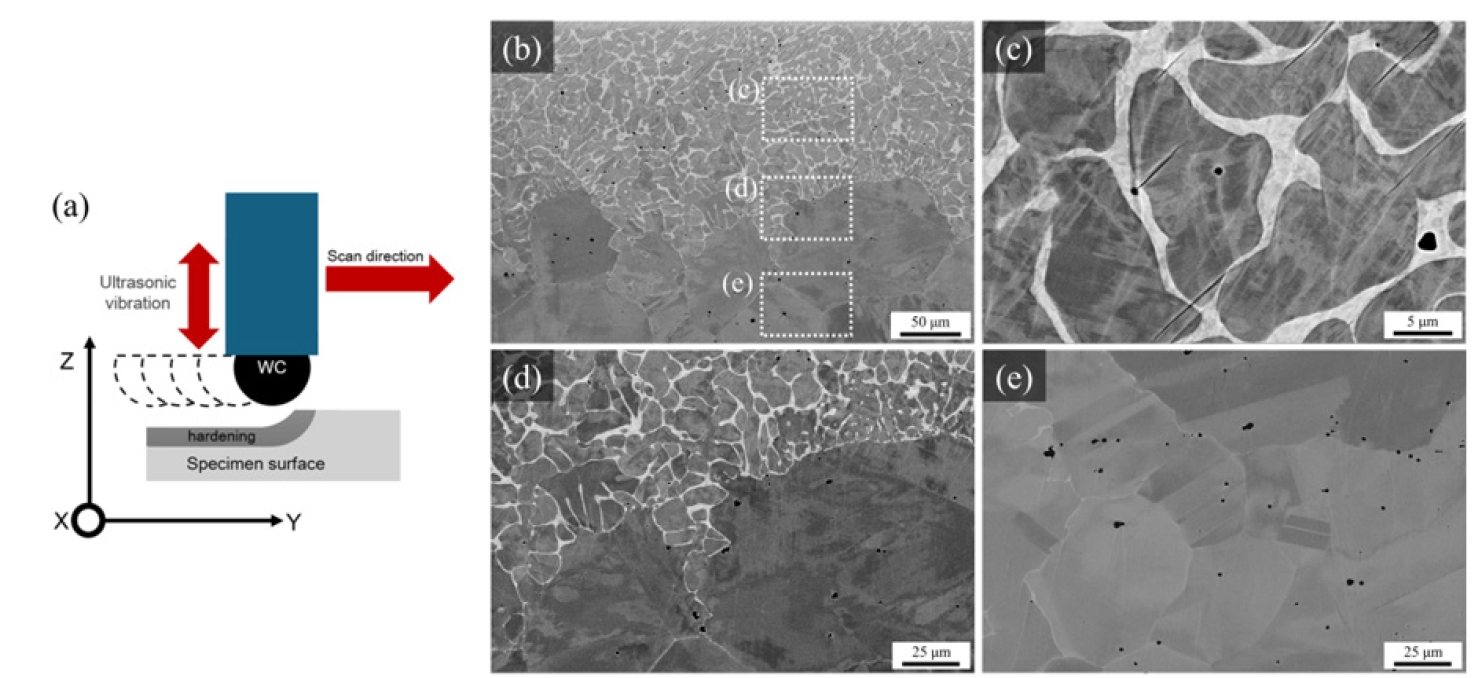
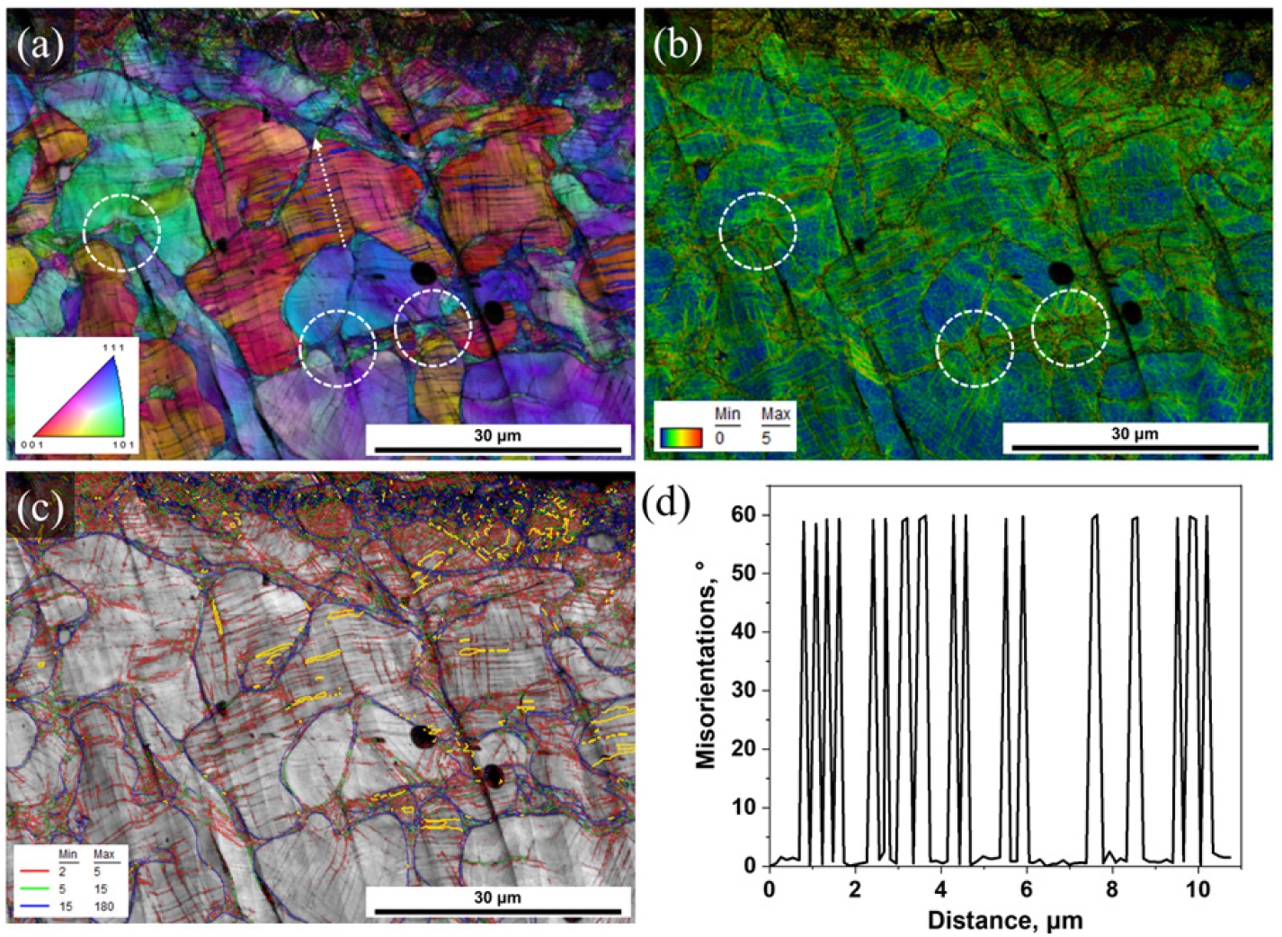


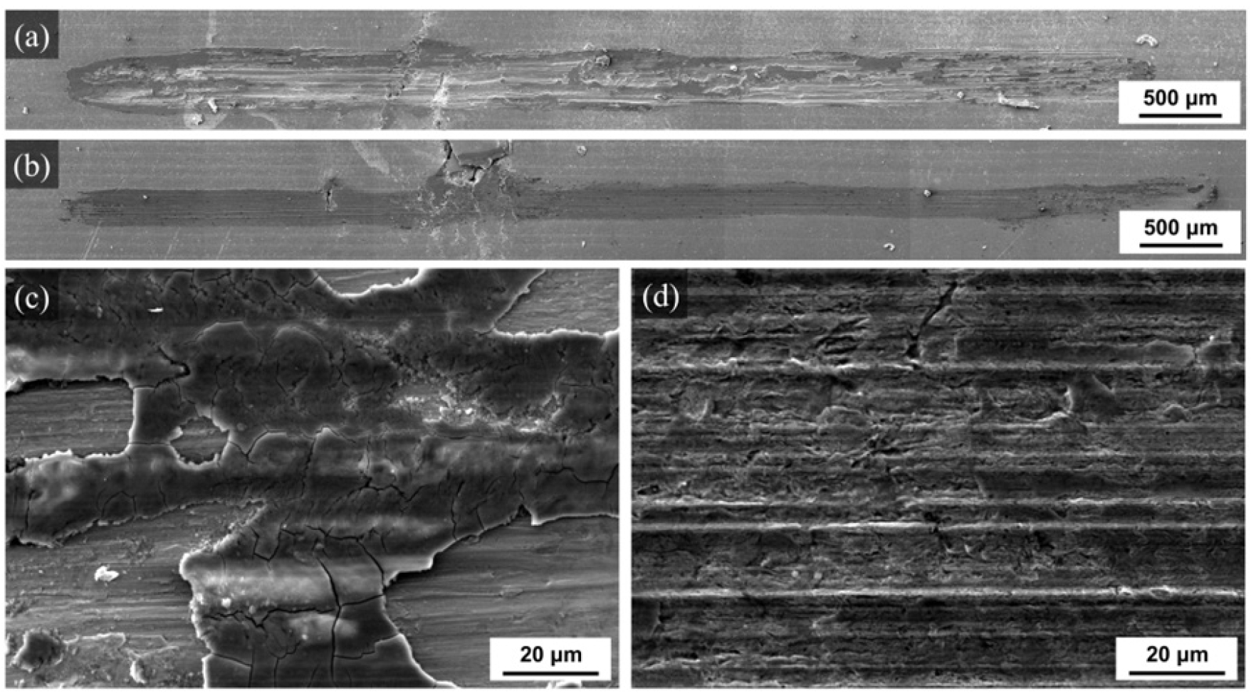
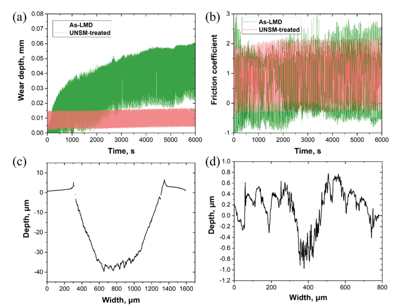


Fig. 1.
Fig. 2.
Fig. 3.
Fig. 4.
Fig. 5.
Fig. 6.
Fig. 7.
Fig. 8.
Fig. 9.
Graphical abstract
TOP
