Articles
- Page Path
- HOME > J Korean Powder Metall Inst > Volume 24(6); 2017 > Article
-
ARTICLE
적층식 제조(Additive manufacturing) 기술동향 - 오지원, 나현웅, 최한신*
- Technology Trend of the additive Manufacturing (AM)
- Ji-Won Oh, Hyunwoong Na, Hanshin Choi*
-
Journal of Korean Powder Metallurgy Institute 2017;24(6):494-507.
DOI: https://doi.org/10.4150/KPMI.2017.24.6.494
Published online: November 30, 2017
한국생산기술연구원 뿌리산업기술연구소 융합공정소재그룹
Advanced Materials and Processing R&D Group, Korea Institute of Industrial Technology, Incheon 406-840, Republic of Korea
- *Corresponding Author: Hanshin Choi, +82-32-850-0135, +82-32-850-0401, hschoi@kitech.re.kr
© The Korean Powder Metallurgy Institute. All rights reserved.
- 1,831 Views
- 11 Download
- 7 Crossref
Abstract
- A three-dimensional physical part can be fabricated from a three-dimensional digital model in a layer-wise manner via additive manufacturing (AM) technology, which is different from the conventional subtractive manufacturing technology. Numerous studies have been conducted to take advantage of the AM opportunities to penetrate bespoke custom product markets, functional engineering part markets, volatile low-volume markets, and spare part markets. Nevertheless, materials issues, machines issues, product issues, and qualification/certification issues still prevent the AM technology from being extensively adopted in industries. The present study briefly reviews the standard classification, technological structures, industrial applications, technological advances, and qualification/certification activities of the AM technology. The economics, productivity, quality, and reliability of the AM technology should be further improved to pass through the technology adoption lifecycle of innovation technology. The AM technology is continuously evolving through the introduction of PM materials, hybridization of AM and conventional manufacturing technologies, adoption of process diagnostics and control systems, and enhanced standardization of the whole lifecycle qualification and certification methodology.
- 공학은 사회의 다양한 요구를 충족하는 제품과 서비스를 효율적인 방식으로 제조하고 제공하는 방법을 끊임없이 제시 하고 있다. 역사를 거슬러 생산기술은 연속적인 혁신 (continuous innovation)의 형태로 진화하거나 불연속적인 혁신 (disruptive innovation)을 통해 창조적 파괴를 통해 새로운 패러 다임을 제시하였다. 3차원 프린팅(3 dimensional printing) 기술 로 더 잘 알려진 적층식 제조기술(AM: additive manufacturing) 은 3차원 구조를 가지는 제품을 제조하는 생산기술로 그 림 1[1-6]에 제시한 바와 같이 수 mm 이하의 초소형 제품 에서 독특한 디자인의 음식, 복잡한 형상의 건축물까지 다 양한 분야와 크기의 소비재 제품을 생산하는 데 응용되고 있다. 산업재 생산 AM 기술 역시 극 미세 부품생산, 복잡 형상 부품생산에서 부품을 포함한 최종 시스템의 생산 (CAD to SYSTEM)까지 다양한 영역에서 시장진입을 위한 연구 활동이 전개되고 있고, 다양한 사업모델을 통해 산업 생태계를 확장하기 위한 노력이 이루어지고 있다.
- Koren은 The Global Manufacturing Revolution(Wiley) [7]에서 시대에 따른 자동차 산업의 제조 방식의 변화를 통해 제조업의 패러다임의 전환을 고찰하고 이를 그림 2와 같이 나타냈다. 사회적 요구, 시장의 특성 변화에 따라 제조 기술의 패러다임은 craft production→mass production→ mass customization→personalized production의 단계를 거친 다고 제시하고 있다. 이러한 패러다임의 전환은 제조기술 의 발전이 구동력이 되고 있다. 실제로 포드 생산방식은 대량생산을 통해 제품의 생산성과 경제성을 낮추었고, 이 후 컴퓨터를 통한 자동화 기술과 제조기술의 결합은 플랫 폼에 기반한 유연생산기술을 통해서 기존의 표준화된 제 품의 대량생산 방식으로부터 부분 혹은 전반적으로 맞춤 형 제품을 생산하는 기술로 전환되었다. 향후 패러다임은 공급자 중심에서 소비자 중심으로 시장이 전환되고 이에 따라서 디자인, 성능, 가격, 제품 수량, After Service(AS) 등에서의 불확실성을 극복할 수 있는 새로운 생산기술을 요구하며, 이는 정보통신기술과 새로운 제조 방식의 결합 을 필요로 한다. AM 기술은 생산기술의 기저를 중앙 집 중화된 대량생산(centralized mass production) 방식에서 대 량 맞춤형 분산 생산(distributed mass customization) 방식 으로 근본적으로 변화시킬 수 있는 잠재력이 큰 미래기술 이다. 현재 AM 기술은 기술적 완성도가 낮아 성장기 진입 이 지연되고 있다. 그러나 혁신 기술의 확산 주기(innovation technology adoption lifecycle)에서 보듯이 AM 기술 역시 산 업계 확산에 있어 간극(chasm)을 유발하는 주요한 문제를 인식하고, 공유하고, 이를 해결하는 실용성 높은 해법을 제 시하는 과정을 필요로 한다. 산업화 주기를 단축하는 효과 적인 방법은 ‘결국 산업 생태계가 얼마나 빠르게 두터워질 수 있는가’에 있다고 할 수 있다. 실제로, AM 특허기술의 보유자 분석결과는 지금까지의 AM 기술이 주로 공급자인 장비 개발자와 산업제품 공급망의 최종소비자가 주를 이루 었고, 절대 다수를 구성하는 소재, 부품 생산자의 참여가 부 족한 상황이다. 따라서 AM 산업생태계에 다양한 참여자가 발생하고, 서로 다른 영역의 참여자 간 연계된 문제해결 활 동을 수행한다면, 소위 네트워크 효과(network effects)에 의해 빠른 속도로 현재의 AM 기술에 제기되는 문제들을 효과적으로 해결할 수 있을 것으로 판단된다.
- 본 분석에서는 AM 기술의 개념에 대한 간략한 소개와 제품화 전 과정에서의 AM 기술 구조 및 개발현황을 소개 하고자 한다.
서 론
- 이미 우리는 종이나 천 심지어 금속 포일 등 2차원 평 면에 다양한 기호, 그림, 문자 등을 출력하는 2차원 프린 팅에 익숙해 있다. 2D 프린팅 과정을 다시 짚어보면, 우선 출력하고자 하는 대상을 다양한 장비와 프로그램을 이용 하여 생산한다. 이 과정은 직접 컴퓨터 프로그램을 이용하 여 생성하거나 웹 상에서 다운로드 하거나, 아니면 스캐너, 사진기 등을 이용하여 출력 가능한 형태의 파일로 만드는 과정이 진행된다. 프린터는 전송된 2차원 이미지 정보를 1차원의 선으로 세분화하여 한 줄씩, 한 줄씩 2차원 평면 에 출력하는 과정을 통해 출력물을 완성한다. 2차원 출력 물의 품질과 출력속도 등은 프린팅 방식, 프린터의 해상도, 출력조건 등에 따라서 달라진다. 결론적으로, 최종제품을 부피를 가지고, 직접 만질 수 있는 3차원의 형태로 출력하 는 AM 기술을 평면 출력물을 생산하는 2D 프린팅 기술 과 비교하면, 최종 제품의 형상이 다르지만 출력 전 과정 에서 근본적으로 상동성(homology)을 가지는 것을 알 수 있다. 이러한 상동성은 향후 3D 기술의 발전방향과 사업 모델을 유추하는 데 있어 매우 중요한 관점이 된다. 지금 까지, 대중적 이해도를 높이기 위해서 주로 사용된 3D 프 린팅 기술이라는 용어는 현재 표준화에 따라 AM 기술로 정의되었다(표 1). ASTM F 2792-12a[8]에는 AM 기술을 최종적으로 만들고자 하는 제품의 3차원 모델을 2차원 파 일로 분해하고 분해된 각각의 2차원 패턴을 순차적으로 컴퓨터를 이용한 제조기술을 적용하여 층층이 쌓아서 최 종적으로 제품화하는 기술로 정의하고 있으며 지금까지 매우 다양한 기술이 산업과 연구계를 통해서 개발되고 소 개되고 있다.
AM 기술
Definitions and synonyms of AM
- AM 기술은 적층방식으로 제품을 제조하는 방식이다. 따라서 제품의 크기에 따라 적층전략을 차별화하는 것이 효과적이다. 예를 들어, 거대한 건축물을 적층하는 경우 미세한 적층을 반복하는 것 보다는 단위 적층을 크게 하 여 빠른 속도로 적층이 완성되는 것이 바람직하며 반대로 미세한 제품은 제품의 형상을 구현하기에 충분히 작은 적 층패턴을 이용해야 한다. 이 관점에서 AM 기술을 우선 제 품 크기별로 분류한다. 제품의 크기에 따라서 마이크로 AM (micro-AM), 일반 AM(general AM), 건축 AM(construction AM) 기술이 있다. Vaezi 등의 리뷰 논문[9]에서는 마이크로 AM 기술을 scalable AM, 3D direct writing, 그리고 hybrid AM 3가지의 세부 그룹으로 분류하였고, 각 그룹의 구성 기 술에 대해서 요약하였다. 건축 AM 기술인 Pegna, Contour Crafting, Concrete Printing, D-Shape 등의 기술이 참고문 헌[10]에 잘 정리되어 있다. 본 리뷰 논문의 상세 기술분 류는 일반 AM 기술로 한정한다. 일반 AM은 다양한 기술 개발자가 다양한 공정 개념을 구현한 독자적인 기술을 제 시하고 있다. AM 기술의 분류는 AM 기술의 개념을 정립 하고 이해하는 데 도움이 되며, 다양한 기준에 따라 기술분 류 체계가 제시될 수 있다. 미국재료시험협회(ASTM) 표준 분류체계에서는 수많은 AM 기술들을 공정개념을 기준으 로 7개의 세부그룹으로 구분하였고, 이를 표 2에 요약하 였으며, 이를 표준 분류체계로 받아들이는 추세에 있다. 표준 기술분류는 기술을 이해하는 데 도움이 되고, 다른 사람과 정보를 교환하는 과정에 불필요한 오해를 줄일 수 있는 장점이 있다, 그러나 표준화의 잠재적인 역효과는 사 람들에게 표준분류 체계의 틀 내에서 기술을 이해하게 하 여 새로운 기술에 대한 창의적 개발활동을 위축할 수 있 다는 점을 지적한다. 아울러 소재별, 소재의 공급방식별 혹은 공정과정의 물질의 상변화를 중심으로 기술을 분류 하는 것이 가능하므로 다양한 분류체계를 시도해서 관련 기술개발 추이를 이해하고 특정분야의 기술개발 및 시장 진입 전략수립에 활용하는 것이 바람직하다.
- 적층기술의 적층공정 중심의 기술개념에 따른 7대 분류 와 별도로 소재별 적층제조기술의 분류는 크게 폴리머, 금 속, 세라믹 적층제조기술로 구분할 수 있다. 표 3에는 소재 별 적층제조기술의 기술 상용화 현황을 나타낸다. 적층이 가능하도록 하는 소재의 특성(consolidation mechanism)으로 폴리머의 경우 용융-응고, 화학경화, 광경화 등의 기구가 존 재하며, 금속의 경우 용융-응고, 소결, 기계접합 등이 가능 하며 세라믹의 경우에는 용융-응고, 소결, 상온 수화반응 등이 존재한다. 이러한 소재의 특성은 금속 용융-응고 적 층을 이용하여 금속 소재부품을 생산하는 분말 베드 적층 제조기술과 같이 대상제품소재 자체의 적층기구를 활용하 는 방법과 금속분말을 화학경화를 발생하는 폴리머 바인 더를 이용하여 성형체를 제조하는 금속 바인더 적층제조 기술과 같이 타 소재의 적층기구를 목적소재의 성형체 제 조에 활용하는 방법이 존재한다. 표 4에는 적층제조기술 에 사용되는 소재의 예를 요약하였다.
AM 기술 분류
AM standard technology classification by ASTM F2792-12a[8]
Status of commercialization of technology of materials and additive mechanism
Materials for AM technology
- AM 기술은 기존의 실물제조기술과 디지털기술이 융합 된 특성을 가지며, 소품종 대량생산 시장보다 대량 맞춤형 생산에 강점을 가지는 기술이다. 향후 시장의 구조는 기존 공급망과 다른 유형으로 전개될 것으로 보이며 불특정 소 비자와 불특정 생산자가 정보통신기술(ICT: Information Communications Technologies) 채널을 통해서 실시간 공 급망을 생성하게 될 것이다. 그림 3에는 이러한 개인 맞춤 형 휘발성 시장을 충족하는 공급망의 예상도를 나타냈다. 이러한 공급망을 충족하기 위해서 제품 제조기술은 매우 단순화된 공급체계를 갖추어야 하며 현재 기준 AM 기술 이 가장 적합성이 높다. 그림 4에 나타낸 것처럼 AM 공 급망 기술의 구조는 크게 생산하고자 하는 제품의 3차원 모델을 최적화하고 적층제조에 적합한 형태로 변환하는 기술(DfAM: design for additive manufacturing)과 전주기 정보를 생성하는 디지털 기술, 대상 모델을 실물로 적층제 조하고 후공정을 통해서 최종 제품화하는 기술, 그리고, 이러한 전 과정을 통해서 생산된 모델과 제품을 평가하고 인증하는 기술로 구성된다.
- 4.1. 디지털 기술
- 수요의 발생에서 최종적으로 제품을 생산, 사용, 폐기하 는 전 과정의 디지털 정보를 생성, 저장, 유통하는 데 요 구되는 기술을 디지털 기술로 정의할 수 있을 것이다. 제 품의 생산과정까지로 범위를 줄이는 경우 AM 기술과 관 련한 디지털 기술은 크게 제품설계, Pre-AM, 그리고 AM 과정의 디지털 기술로 구분할 있다. 그림 5와 표 5에는 한 개의 제품이 최종적으로 생산되는 과정을 모형화한 절차 를 나타낸다. 상품설계 과정(Product Design)은 기존의 컴 퓨터 지원설계(CAD: Computer Aided Design) 프로그램을 이용한 디자인이나 스캐너를 이용한 역설계를 통해서 원 형모형을 준비하고, 이를 AM의 기술적 장점을 적용하여 최적화하는 단계이다. 기존 제조기술과 달리 형상의 자유 도가 높으므로 형상(topology)과 중량을 격자구조를 통해 서 최적화하는 과정 및 이를 통해서 형성된 모델의 제품 특성을 전산모사하는 과정을 반복적으로 수행한다. 최종 적으로 확정된 3D 모델은 프린팅에 적합한 유형으로 변환 /최적화하는 Pre-AM 단계를 거친다. 이 과정에서는 컴퓨 터 지원 설계의 파일 포맷 종류인 스테레오리소그래피 (STL)로 변환/검증이 필수적이며 필요에 따라서(상품이 장비보다 큰 경우) 최종 상품을 출력 가능한 크기와 출력 의 편의성이 고려된 파트로 세분, 세분된 파트를 조립하는 결합부 형상생성의 전처리를 거치게 된다. 기술에 따라서 기하적 형상지지, 열 배출경로 및 후공정을 위한 지지체를 설계하고 부과하는 기술이 적용된다. 실제 양산에서는 복 수의 서로 상이한 형상을 가지는 상품을 일정한 적층 부피 공간내에 채우는 과정이 필요하고 이 과정에 배치와 방위 및 상호간의 연결 등을 최적화하는 과정이 필요하다. 아울 러 일련의 pre-AM 과정은 전산모사의 과정을 통해서 적합 성 검토를 수행하게 된다. 적층제조(AM)과정에서는 실시 간 공정의 진단을 통해서 공정을 모니터링하고 적정한 공 정 조건이 이루어지도록 실시간 공정변수를 조절하는 기 술이 활용되고 있다.
- 금속 AM은 고밀도 열원을 이용하는 경우가 일반적이므 로 pre-AM과 공정 예측을 통해 대상 모델과 일치성이 높 은 제품의 생산에 대한 신뢰성을 높이는 디지털 기술의 확보가 현재 상용화된 기술의 제품 특성 불확실성을 극복 할 수 있는 현실적인 대안을 제시할 것이다. 국부 영역에 고밀도 열원이 조사되는 경우 온도의 구배가 발생하게 되 고 잔류응력의 발생, 국부변형 및 소재에 따라 균열을 발 생할 수 있어 3차원 제품화 과정에서 열의 제어가 필수이 다. 실제로 3D 모델링과 AM 제품의 불일치성을 개선하기 위한 접근방법으로 3D 모델을 AM 공정과정에서 발생할 수 있는 변형을 고려하여 수정하는 절차를 거치거나, 공정 과정에서 적층경로와 공정변수 최적화를 통해서 변형을 최소화하는 접근방법이 시도되고 있다. AM 공정변수와 적층경로 및 support 구조에 따른 3D 형상의 발생을 시뮬 레이션을 통해서 예측하고자 하는 연구가 활발히 진행되 고 있다. 대표적으로 레이저 열원을 이용한 AM의 공정과 정에서 온도분포와 상변화를 3D 유한요소해석을 통해서 예측한 연구[11]가 있다. 그러나 대부분의 시뮬레이션이 레이저 용접의 해석을 기반으로하고 있어, 분말을 이용한 조건과 차이를 유발할 수 있다. 열원의 조사에 따라 상변 화를 통해 용융풀이 형성되는 경우 분말 베드에서 용융풀 의 유동이 발생하게 되며, 용융풀과 분말간의 상호작용이 고려되야 한다. 벌크소재와 다른 분말베드의 레이저와의 반응을 반영하기 위해서 ray tracing 모델링 접근방법[12] 이 제시되었다. 레이저 빔이 조사되는 과정에서 분말입자 에 흡수 혹은 반사가 발생하고 반사된 빔이 다시 다른 입 자와 충돌하는 과정을 연쇄적으로 추적하는 방법을 적용 하였다. 또한 이 과정에서 분말의 용융과 수축, 고상분말 및 가스상의 거동을 동시에 해석하여 온도구배, 응력구배 및 미세조직의 발생에 대해서 더 정확한 예측이 가능해야 한다. 특히 분말베드의 열전도와 관련한 기초이론과 불특 정한 분말의 불규칙한 충진에 대한 모형화가 신뢰성 있게 제시되어야 한다. 대량 맞춤형 시장에서 AM 기술은 복잡 형상의 다양한 소량제품을 동시 생산하게 될 것이며 이와 관련하여 디지털 기술의 중요성이 매우 높은 반면 경제성 과 생산성의 장벽요인이 될 수 있다. 따라서 전주기 디지 털기술이 높은 신뢰성과 함께 신속성, 편의성, 응용성 및 경제성을 확보할 수 있는 소프트웨어의 개발이 필요하다. 실제로 세계적으로 디지털 기술 분야의 기술개발과 보급- 확산 및 클라우드 환경하에서의 프로그램의 시장 지배력 을 높이기 위한 경쟁이 활발히 전개되고 있다.
- 4.2. 실물제조기술 4.2.1.
- Bourell 등이 작성한 참고문헌[13]에는 AM 기술의 역사 가 잘 요약되어 있고 이를 통해 현재의 AM 기술은 150년 이상의 오랜 기간 동안 많은 연구자가 수행한 다양한 연 구가 누적된 사회적 성과물임을 알 수 있다. 제조산업분야 에서는 AM과 함께 Rapid Prototyping (RP), Rapid Tooling (RT), Rapid Manufacturing (RM) 기술이 사용되고 있다[9]. 기존의 벌크소재의 기계가공 방식이 아닌 적층식 기술의 본격적인 기술 개념정립이 이루어진 1900년대 후 반에는 컴퓨터를 이용하는 컴퓨터 이용설계 및 컴퓨터 이 용제조(CAD/CAM: computer aided manufacturing) 기술이 제조산업에 접목되면서 모델을 설계하는 과정에서 제품화 하는 과정까지 전 과정에 소요되는 시간을 비약적으로 줄 일 수 있게 한다는 장점이 부각되면서 RP 기술이 정립되 었다. 동시에 벌크소재의 기계가공 방식으로 불가능한 형 상을 구현 가능하다는 점이 장점으로 부각되었고 다양한 툴의 생산에 적용되는 RT 개념이 도출되었다. 이후 속도 와 디자인 자유도외에 제조된 제품의 정밀도, 성능 등이 크게 개선되면서 완성품을 생산하는 RM 개념이 제시되었 고 제품개발 단계나 소량제품생산에 적용되었다.
- 상품개발에서 상품설계 단계는 매우 중요한 출발점으로 상품의 기능적인 면과 함께 제조전략 수립을 동시에 설계 하게 된다. 그림 6에 도시한 것처럼 상품모형의 제작 RP 는 상품 디자인에 충실한 개념모형(concept model)과 제조 과정의 상품의 기능을 정의하기 위한 목적의 기능모형 (functional model)로 구분된다[14]. AM 기술의 발전은 기 능모형의 적용이 가능하여 상품설계의 신뢰성을 높이고 있다. RP의 적용은 주로 건축, 자동차, 조선, 항공 분야 등 주로 대형의 제품설계에 활용되고 있고, 파트화된 모형의 조립과정, 보수/유지 적합성, 기능성 파트를 이용한 성능 평가 등에 활용되고 있다. 실례로 에어버스는 AM 기술을 소형의 모형 항공기 제작에 활용하여 공기역학적 디자인 최적화 연구와 비행과정의 정보 추출에 활용하고 있다. AM 기술을 툴 생산에 활용하는 기술은 이미 많은 상용화 가 소개되고 있다. 대표적으로 금형을 제조하는 기술[15] 은 제품화 과정에서 소요되는 금형을 AM 기술로 적용하 므로 전주기 측면에서 RT기술로 간주할 수 있다. 이외에 도 모래를 이용한 바인더 젯팅 기술은 대형 주조물의 사형 을 목형 없이 직접 생산하는 기술[16]로 활용되고 있다. 소 비재 분야에서 소실모형 주조와 관련한 모형제작은 폴리 머 압출 적층제조나 왁스를 이용한 material jetting 기술 [17]을 적용하고 있다. 건축부재 생산과 관련해서도 콘크 리트 건축부재를 폴리머를 이용하여 대형 패턴을 제조하거 나 Expended Poly Styrene(EPS)를 이용한 sheet lamination 공법을 적용하여 몰드를 제조하는 기술이 RT 기술로 활용 되고 있다[18]. 최종 제품을 직접 제조하는 기술분야는 소비 재 시장, 바이오 디바이스 시장 및 산업소재부품이 있다. 폴 리머를 이용한 기술분야는 이미 성장기에 진입한 반면 금 속 AM 시장은 도입기에 있다고 볼 수 있다. 선택 가능한 소재의 종류와 가격, 장비의 크기, 제작속도와 가격, 제품 의 품질과 경제성 등이 여전히 시장확장에는 한계를 가지 며, 산업소재부품의 경우 제품과 생산의 신뢰성에 대한 문 제가 해결 되어야 할 문제이다.
- 실물제조와 관련한 AM 기술의 요소는 크게 소재와 장 비로 구성된다. 표 6에는 현재 글로벌 주요 장비, 소재 공 급자를 금속기술을 중심으로 조사한 결과를 나타냈다. 점 차로 시장 참여자가 확대되는 양상을 나타낸다. 특히 소재 의 경우 장비 공급망에 주문자 생산방식의 공급망을 구성 하다가 점차로 독립적인 상표로 시장에 참여하는 기업이 증가하는 추세이다. 금속소재의 경우 Pure Ti/Ti-6Al-4V, Co alloys(CoCr, CoCrMo), Al alloys(AlSi, AlSiMg, AlMgSc, 7XXX), Ni alloys(IN 625, IN 718), Fe alloys(316L STS, Maraging, 17-4 PH) 등이 주력시장을 형성하고 있으나, 다양 한 공정기구를 가지는 장비의 개발과 함께 소재 선택성이 크게 확장되고 있다. 표 7에는 금속기지 복합소재를 이용한 AM 기술의 개발 예시를 나타냈다.
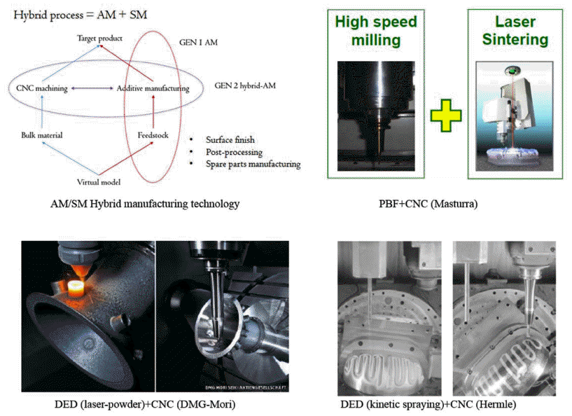
- AM 장비기술 개발은 크게 저가격화, 대형화, 하이브리 드화, 고속화 및 지능화로 전개되고 있다. 개인용 폴리머 장비는 이미 개인 조립이 가능한 장비 하드웨어와 신속한 프로토타입 복제기(RepRap: the Replicating Rapid Prototyper) 및 아두노이 기반 개방형 플랫폼과 연계를 통해 저 가격화를 실현하고 있다. 적용 가능한 상품의 선택성은 소재외에도 장비의 크기에 따라서 제한되므로 장비의 대형화가 전개 되고 있다. 그림 7에는 금속 적층제조 기술에서 장비제조 사별 장비의 가용 적층제조 공간과 가격을 나타낸다. 장비 의 하이브리드화는 그림 8에 대표적인 상용기술을 나타냈 다. 하이브리드 적층제조 기술은 1세대 적층제조 장비가 가지는 품질의 한계(치수정밀도, 형상, 표면조도)를 극복 하는 기술로 주로 적층제조 기술과 컴퓨터 수치제어 (CNC: Computer Numerical Control) 가공기술을 동일한 플랫폼에서 선택적으로 조합하여 수행하는 기구가 구현된 기술이다. Powder Bed Fusion (PBF)-CNC 하이브리드 장 비의 경우 기존 PBF 기술의 치수정밀도와 표면조도의 한 계를 극복하고 구조적인 측면에서 후 가공이 어려운 내부 구조를 공정과정에서 가공하여 정형 생산이 가능하게 하 는 장점이 있다. Directed energy deposition (DED)+CNC 하이브리드 장비는 적층제조 공정기술이 가지는 정밀도와 생산성의 반비례 관계를 극복하는 기술로 높은 출력조건 으로 두꺼운 적층물을 통해 빠르게 적층제조 하고 CNC 공정을 통해서 형상과 표면조도를 충족하는 장점이 있다. Kinetic spraying 공정과 CNC 적층제조 기술은 노즐을 통 해서 국부영역에 높은 운동에너지를 가진 입자를 가속하 고 충돌-변형 과정을 통해서 적층을 구현한 후 CNC 가공 을 통해서 형상을 제조하는 기술이다. 적층제조의 생산성 은 장비의 고속출력에 직접적으로 의존한다. 금속 베드 용 융 적층제조 장비에서는 고밀도 열원의 고 출력화를 통해 스캔 속도를 높이거나 그림 9처럼 복수의 레이저를 이용 하는 장비(galvano-mirror 방식)를 통해서 생산성을 개선하 고자 한다. 예시로 독일 SLM Solutions 社는 복수의 레이 저-스캐너 시스템을 이용한 멀티 레이저 PBF 장비를 통해 서 생산성 개선을 제시하고 있다. 또 다른 멀티 레이저 시 스템은 기존은 방식이 아니라 gantry 방식의 이송기구를 적용한 멀티 레이저 시스템을 채용하고 있다[27]. 독일 프 라운호퍼 레이저기술연구소(ILT) 및 영국 캠브리지 대학 의 Engineering and Physical Sciences Research Council (EPSRC)는 멀티 레이저를 배열한 광학계를 이송하면서 on/off 방식으로 spot 형태의 비드를 형성하면서 적층제조 하는 기술을 개발하였다. 장비의 지능화는 공정환경을 지 속적으로 최적화된 조건으로 유지하는 자율운영기술이다. 이를 위해서 각종 센서를 통해 공정과정에서의 목표 물성 을 실시간 모니터링하고, 분석 후 공정제어에 피드백하는 closed-loop 시스템화 되고 있다. 금속분말 PBF기술에서는 분말베드의 거시영역에서의 안정성 모니터링 하는 기술 [28]과 용융 풀(melt pool)의 형상과 온도를 주요 모니터링 인자로 하는 미시진단기술[29]이 있다. AM 기술과 관련 한 모니터링 기술의 현황은 Everton 등의 리뷰 논문에 잘 정리되어 있다[30].
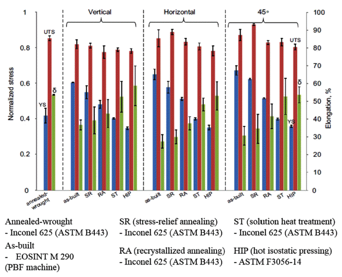
- 현재 기술수준에서는 적층제조 상태의 제품(as-built product)은 치수정밀도, 표면조도, 미세조직, 상조성의 불균 일성이 높아 후속 공정을 통해서 최종 제품화가 전개된다. 실후 공정기술은 추가적인 제조시간과 제조비용을 유발한 다. 실제로 복잡한 형상의 소량 적층제조 제품의 품질을 기존 산업기술의 품질과 동등한 수준으로 구현하기 위한 후공정 비용은 적층제조 비용의 60%-300% 수준이 소요 된다고 추정된다. 후 공정기술은 응용분야에서 요구되는 특성을 충족하기 위해서 열처리, 열-기계처리, 가공처리, 표면처리 기술을 선택적으로 조합한다. 실제로 용융-응고 기구를 이용하여 적층제조(as-built)된 상태의 제품은 국부 용융-응고를 통한 비드의 방향성을 가지는 반복적 적층의 결과로 물성의 이방성을 가지며, 급속응고와 재가열에 의 해 불균일한 미세조직을 나타내므로 후열처리 혹은 열기 계적 후처리 기술을 통해 상조성, 미세조직 및 이방성을 제어할 필요가 있다. 그림 10[31]에는 Inconel 625 분말을 레이저 분말베드 용융 적층제조한 샘플의 기계적 특성을 적층방위와 후처리 공정에 따라서 비교한 특성을 나타낸 다. As-built 상태에서 방위에 따른 이방성을 나타내는 반 면 재결정화 이상의 온도에서 후열처리하는 경우 주상정 구조에서 등축정 구조로 결정의 변화가 발생하고 이를 통 해 균질화가 이루어지는 반면 결정성장에 따른 강도의 감 소가 발생한다. Sanz 등 은[32] 레이저 분말베드 용융 적층 제조 기술을 통해 제조된 Maraging steel, Inconnel 718, 그 리고 CoCrMo 합금 파트의 잔류응력과 shot peening과 후 열처리에 따른 표면 잔류응력(x-선 회절분석)의 변화를 측 정하였고, 표준화된 형상을 가지는 파트에서도 적층제조 상태에서 소재 종류와 파트내 적층위치에 따라서 상이한 잔류응력값을 나타내며 후공정을 통해 잔류응력을 제어할 수 있음을 보고하고 있다. 제품의 치수 정밀도와 표면조도 등의 품질은 가공기술을 통해서 개선한다.
- 적층제조기술은 근원적으로 유선형의 3차원 모델을 2차 원의 형상으로 세분화(slicing)하고 이를 2차원 패턴화 하 는 방식을 높이 방향으로 반복하여 수행하므로 소위 계단 효과(stair-case)가 발생하게 된다. 아울러 적층제조 과정에 서 자중이나 열응력에 의한 변형이 발생하는 경우 형상과 치수의 정밀도가 낮아지게 된다. 따라서, 최종제품의 형상 과 표면조도를 구현하기 위해서 적층제조 완료된 샘플을 가공처리 한다. 기계가공기술은 CNC 기술을 이용한 가공 과 연마입자를 이용한 블라스팅 기술[33], CO2를 이용한 가공기술[34]등이 제시되고 있다. 소재부품이나 소재부품 생산을 위한 각종 툴의 열 제어를 위해 적극적으로 활용되 고 있는 conformal cooling 채널은 복잡한 냉각계통을 가지 고 있어 기존의 기계가공을 적용하기 어렵다. 이러한 내부 구조의 가공기술로 abrasive flow machining 기술 및 초음파 를 이용한 국부가공 기술 등이 제시되고 있다. Abrasive flow machining 기술[35] 은 연마입자가 분산된 폴리머 연마 페이스트를 가압하여 유동을 유발하고 이 과정에서 연마입 자가 표면의 입자, burr 등을 제거하는 과정을 토해 연마하는 기술이다. 초음파 가공기술(ultrasonic cavitation abrasive finishing)은 액상 매질 내에서 초음파를 이용하여 피삭재의 표면을 연마하는 기술로 버블붕괴에 따른 효과와 매질내 연마입자와 피삭재 표면 상호작용[36]을 이용한다. 전기화 학적 방법을 통한 표면처리기술은 대표적으로 전해연마 기술(electro-polishing)이 적용되고 있다. 복잡한 외부형상 과 내부구조를 가지는 적층제조물에 대한 전해연마 공정 기술은 균질한 표면조도와 전해연마를 통한 두께 감소가 제어 가능한 공정변수와 전극형상 및 전극배열기술[37]을 요구된다. 독일의 EOS 社와 스위스의 BESTinCLASS 社의 공동출자 벤처기업인 First Surface 社가 상용화한 Micro Machining Process (MMP) 기술은 기계적 연마와 화학적 연마를 혼용한 기술이다. 피삭재의 표면정보를 획득하고 분석한 후 수만개의 마이크로 커터에 의해 정밀하게 가공 하는 기술로 복잡한 형상의 피삭재를 치수변화 없이 정밀 가공(Ra 0.015 um)이 가능하다고 보고하고 있다.
- 4.3. 평가/인증
- 표 8에는 소재, 제조 및 인증과 관련한 주요 이슈를 요약 하였다. AM 기술의 산업화와 관련하여 품질평가와 인증의 문제가 중요하다. 기술 자체가 지향하는 바가 소량 다품종 제품으로 소량의 제품에 대한 경제적이고 생산적인 평가방 법이 부족하고, 기술의 불확실성이 높고 수명이 짧아 기존 의 인증체계에 직접 적용하기 어려운 상황이다. 특히 항공 우주, 바이오, 건축과 같이 높은 수준의 인증체계가 요하는 산업분야에서는 시장진입의 선결요건이 인증이다.
- AM 기술의 인증은 소재, 공정, 품질, 생산자를 정확하 게 평가할 수 있는 표준화된 평가절차가 우선적으로 필요 하다. 이러한 맥락에서 세계적으로 AM 기술은 표준화가 빠르게 전개되고 있다. 표준화는 크게 기존의 표준을 AM 기술과 연계하는 활동과 AM 기술에 요구되는 기준을 표 준화하는 활동으로 구분할 수 있다. 이러한 표준화 활동은 용어에 대한 정의, 소재에 대한 평가방안, 공정기술에 대 한 기준, 파일 포맷에 대한 기준, 파트 생산절차에 대한 기 준, 파트 특성평가, 후공정 파트 특성평가에 대한 절차 및 보고절차에 대한 표준 등 광범위한 분야에서 동시적으로 전개되고 있다. 표 9과 10에는 분말평가, 파트 기계특성평 가의 예시를 나타낸다. 분말을 이용한 적층제조 기술에서 분말은 공정이나 공정 후 제품의 특성에 직접적인 영향을 미치는 주요인자로 적층제조와 관련한 분말특성의 표준 가이드라인은 ASTM F3049-19[38]에 규정되어 있다.
- 표 11에서처럼 금속 AM 기술과 관련한 자체 표준으로 는 PBF AM을 이용한 대표 소재 Ti 합금과 Ni 합금의 표 준화가 이루어졌다. 적층제조된 제품의 기하적인 형상의 정밀성 및 표면조도에 대한 평가와 3차원 모델과의 일치 성 평가가 중요하다. 실제로 적층제조 술의 디자인 자유도 (복잡형상, undercut, 비정형, 자연모사, 내부구조)는 생산 기술 중심의 제품설계에서 기능중심의 제품설계가 가능하 게 하는 잠재력을 가진 반면 현재 AM 기술은 치수정밀도, 표면조도, 공정제약성을 보인다. 소량 다품종의 제품생산과 관련해서는 복잡한 형상적인 인자에 대한 정확하고, 빠르 고 경제적인 기술을 제시할 필요가 있다. 실제로 적층제조 된 제품의 특성을 평가하기 위해서 기존의 파괴적인 접근 방법은 경제성과 생산성의 한계를 가질 수 밖에 없으므로 주로 비파괴 검사를 통해서 최종 제품의 특성을 평가하고 자 하는 연구가 활발히 전개되고 있다. 대표적으로, s-built 상태와 후공정 단계별 내부구조를 포함한 제품의 3D 형상정 밀도와 표면특성 평가에 대한 기술은 광학계를 이용한 비파 괴 검사[40], 와전류 탐사[41], 초음파검사[42], Computational Tomography(CT) 기술[43] 등이 주를 이루며 단순 이미지 분석 을 넘어 형상인자, 결함, texture 등을 높은 분해능과 속도로 정량화하는 기술개발이 진행되고 있다. 다른 측면에서는 각 AM 기술과 장비의 기하적 형상 구현 능을 평가하고 공정의 신뢰성을 검증하기 위해서 표준화된 모델을 통해 서 평가하는 방법이 제시되고 있다. 그림 11에는 표준 모 델의 예시를 나타낸다[44].
AM 기술구조
The status and digital technology of AM
AM
Participants in AM technology market
Metal based composite material (Research trends of Laboratory)
| Powder | Powder manufacturing process | AM process |
|---|---|---|
|
|
||
| Fe-C (graphite) | Tumbling mixing (0, 0.4, 0.8, 1.2, 1.6 wt.% C) | Selective laser sintering[19] |
| WC-Co | Granulation (4, 10 wt.% Co) | Selective laser sintering |
| Bronze infiltration[20] | ||
| Invar 36 (Fe-Ni)-TiC | Blended powder (30, 60, 80 wt.% TiC) | Direct metal laser sintering[21] |
| AA6061-Mg-Sn-Nylon | Blended powder (2 wt.% Mg, 1 wt.% Sn, 3 wt.% nylon) | Selective laser sintering |
| AA6061 infiltration[22] | ||
| Cu-Ti-C-Ni | Mixture (planetary ball milling) | Selective laser sintering |
| In-situ carburization[22] | ||
| Invar 36-TiC | Powder mixture (0, 6.6, 14.3, 22.1, 29.4, 52.1 vol.% TiC) | Direct laser deposition[23] |
| Fe-Nylon | Filament (30, 40 vol.% Fe) | Fused deposition modeling[24] |
| IN 625-TiC | Planetary ball mixing (5 wt.% TiC) | Laser metal deposition[25] |
| IN 625-Al2O3 | ||
| IN 625-SiC | Ball mixing (5 wt.% additives) | Laser powder bed fusion[22] |
| IM 625-TiC | ||
| AlSi10Mg-TiC | Ball mixing (5 wt.% TiC nanoparticle) | Selective laser melting[26] |
| Fe-Ti-C | Ball mixing (24.9 wt.% Ti, 5.1 wt.% C) | Laser additive manufacturing |
| (directed energy deposition)[22] | ||
Effect of lamination direction and post-heat treatment on mechanical properties (room temperature tensile strength) of IN625 through melt blown AM technology [31].
Post-AM
Effect of lamination direction and post-heat treatment on mechanical properties (room temperature tensile strength) of IN625 through melt blown AM technology [31].
Major issues for materials, products and certifications
| Issues in Materials | Issues in Fabrication | Issues in Certification |
|---|---|---|
|
|
||
Example of characteristic evaluation of powder
Mechanical properties evaluation and measurement properties[39]
| Division | Deformation behavior | Fracture behavior | ||
|---|---|---|---|---|
|
|
||||
| Tension test, compression test, bearing test, modulus test, hardness test | Fatigue test, fracture toughness test, creep test | |||
|
|
||||
| Properties | ||||
Examples of typical metal lamination manufacturing standards
- 아직 기술적인 완성도가 낮지만 AM 기술은 시장 변화에 따른 새로운 제조 패러다임 전환의 핵심적인 생산 시스템으 로 성장할 것으로 예상된다. 본문에서 기술한 바와 같이 디 지털 기술과 실물제조기술이 융합된 기술인 동시에 ICT 기 반의 공급망을 통해 대량 맞춤형 시장에 최적화된 솔루션을 제공하기 위해서는 상품설계, pre-AM, 생산과정에서의 공 정제어 S/W 등과 같은 디지털 기술과 소재, 장비, AM 공정 제어기술 및 후공정 기술의 최적화를 통한 일치성 높은 실 물제조기술, 그리고, 상품모델, 소재, 장비, 제품 및 생산자 평가/인증 기술을 통한 시장의 신뢰성 확보가 동기화된 형 태로 개발될 필요성이 높다는 것을 강조한다.
맺음말
-
Acknowledgements
- 본 연구는 국토교통부 도시건축연구사업 연구비 지원 (17AUDP-B121595-02)에 의해 수행되었습니다.
감사의 글
- 1. https://multimedia-berichte.technik-und-wissen.ch/Das-Kleinstgedruckte/#Home
- 2. J.I. Lipton, M. Cutler, F. Nigl, D. Cohen and H. Lipson: Trends Food Sci. Technol.., (2015) 43 114.Article
- 3. http://www.arabianbusiness.com/dubai-reveals-plan-forworld-s-first-3d-printed-office-building-597981.html
- 4. http://advancedmanufacturing.org/micro-manufacturingkeeps-shrinking-envelope/
- 5. https://www.nextbigfuture.com/2015/05/three-yearproject-to-enable-titanium.html
- 6. http://www.fabricatingandmetalworking.com/2014/05/large-scale-additive-manufacturing-bigger-is-better/
- 7. Y. Koren, The global manufacturing revolution: productprocess-business integration and reconfigurable systems., John Wiley & Sons, (2010) 80.
- 8. ASTM, F 2792-12a, ASTM International.
- 9. M. Vaezi, H. Seitz and S. Yang: Int. J. Adv. Manuf. Technol.., (2013) 67 1721.ArticlePDF
- 10. S. Lim, R.A. Buswell, T.T. Le, S.A. Austin, A.G. Gibb and T. Thorpe: Autom. Construct.., (2012) 21 262.Article
- 11. P. Bidare, I. Bitharas, R.M. Ward, M.M. Attallah and A.J. Moore: Acta Mater.., (2018) 142 107.Article
- 12. A. Foroozmehr, M. Badrossamay and E. Foroozmehr: Mater. Des.., (2016) 89 255.Article
- 13. D. L. Bourell, J. J. Beaman Jr, M. C. Leu and D. W. Rosen, TURKEY Workshop On Rapid Technologies. (2009.
- 14. A.K. Matta, D.R. Raju and K.N. Suman: Mater. Today., (2015) 2 3438.Article
- 15. A. B. M. Saifullah, S. H. Masood, M. Nikzad and M. Brandt, Reference module in materials science and materials engineering. (2016.
- 16. M. Upadhyay, T. Sivarupan and M.E. Mansori: J. Manuf. Process.., (2017) 29 211.Article
- 17. R. Singh, J. Singh and S. Singh: Measurement., (2016) 78 253.Article
- 18. D.G. Ahn, S.H. Lee and D.Y. Yang: Int. J. Mach. Tools Manuf.., (2003) 43 1447.Article
- 19. A. Simchi: Mater. Sci. Eng. A., (2006) 428 148.Article
- 20. J.P. Kruth, P. Mercelis, J.V. Vaerenbergh, L. Froyen and M. Rombouts: Rapid Prototyping J.., (2005) 11 26.Article
- 21. D.C. Hofmann, S. Roberts, R. Otis, J. Kolodziejska, R.P. Dillon, J.O. Suh, A.A. Shapiro, Z.K. Liu and J.P. Borgonia: Sci. Rep.., (2014) 4 5357.
- 22. H. Choi, J.M. Byun, W. Lee, S.R. Bang and Y.D. Kim: J. Korean Powder Metall. Inst.., (2016) 23 149.ArticlePDF
- 23. A. GA A rd, P. Krakhmalev and J. Bergström: J. Alloys Compd.., (2006) 421 166.
- 24. H.K. Garg and R. Singh: Mater. Sci. Forum., (2014) 808 103.Article
- 25. D.E. Cooper, N. Blundell, S. Maggs and G.J. Gibbons: J. Mater. Process. Technol.., (2013) 213 2191.Article
- 26. N. Kang, P. Coddet, Q. Liu, H.L. Liao and C. Coddet: Addit. Manuf.., (2016) 11 1.Article
- 27. M.Z. Arredondo, N. Boone, J. Willmott, D.T. Childs, P. Ivanov, K.M. Groom and K. Mumtaz: Mater. Des.., (2017) 117 305.
- 28. T. Craeghs, S. Clijsters, E. Yasa and J.P. Kruth, Proceedings of the Solid Freeform Fabrication Symposium Austin. Texas. (2011) p. 212.
- 29. S. Berumen, F. Bechmann, S. Lindner, J.P. Kruth and T. Craeghs: Phys. Procedia., (2010) 5 617.Article
- 30. S.K. Everton, M. Hirsch, P. Stravroulakis, R.K. Leach and A.T. Clare: Mater. Des.., (2016) 95 431.Article
- 31. K. Alena, B. Vladimir, T. Sylvain, C. Cyrille and U. Victor: Mater. Sci. Forum., (2017) 879 1008.
- 32. C. Sanz and V.G. Navas: J. Mater. Process. Technol.., (2013) 213 2126.Article
- 33. http://www.instructables.com/id/3D-Print-Finishing-Technique-for-Improved-Surface-/
- 34. http://www.sciencedirect.com/science/article/pii/S0026065716300327
- 35. E. Uhlmann, C. Schmiedel and J. Wendler: Procedia CIRP., (2015) 31 209.Article
- 36. K.L. Tan and S.H. Yeo: Wear., (2017) 378 90.
- 37. V. Urlea and V. Brailovski: J. Mater. Process. Technol.., (2017) 242 1.Article
- 38. ASTM, F 3049-19, ASTM International.
- 39. J. Slotwinski, A. Cooke and S. Moylan, (2012) National Institute of Standards and Technology, 7847.
- 40. G. Guan, M. Hirsch, Z.H. Lu, D.T. Childs, S.J. Matcher, R. Goodridge, K.M. Groom and A.T. Clare: Mater. Des.., (2015) 88 837.Article
- 41. P. Nanekar, A. Kumar and T. Jayakumar: Case Studies in Nondestructive Testing and Evaluation., (2016) 5 9.
- 42. N.V. Karthik, H. Gu, D. Pal, T. Starr and B. Stucker, 24th International Solid Freeform Fabrication Symposium. (2013) p. 311.
- 43. F.H. Kim, S.P. Moylan, E.J. Garboczi and J.A. Slotwinski: Addit. Manuf.., (2017) 17 23.Article
- 44. S. Moylan, A. Cooke, K. Jurrens, J. Slotwinski and M.A. Donmez, (2012) National Institute of Standards and Technology, 7858.
Figure & Data
References
Citations

- Convolutional LSTM based melt-pool prediction from images of laser tool path strategy in laser powder bed fusion for additive manufacturing
Joung Min Park, Minho Choi, Jumyung Um
The International Journal of Advanced Manufacturing Technology.2024; 130(3-4): 1871. CrossRef - Color evaluation by thickness of interim restorative resin produced by digital light processing 3D printer
Wol Kang, Won-Gi Kim
Journal of Korean Acedemy of Dental Technology.2021; 43(3): 77. CrossRef - Optimization of Metal Powder Particle Size Distribution for Powder Bed Fusion Process via Simulation
Hwaseon Lee, Dae-Kyeom Kim, Young Il Kim, Jieun Nam, Yong Son, Taek-Soo Kim, Bin Lee
Journal of Korean Powder Metallurgy Institute.2020; 27(1): 44. CrossRef - Technology Trend of Additive Manufacturing Standardization
Hanshin Choi, Jinsu Park
Journal of Korean Powder Metallurgy Institute.2020; 27(5): 420. CrossRef - Multi-step Metals Additive Manufacturing Technologies
Ji-Won Oh, Jinsu Park, Hanshin Choi
Journal of Korean Powder Metallurgy Institute.2020; 27(3): 256. CrossRef - Anisotropy in Green Body Bending Strength due to Additive Direction in the Binder-Jetting Additive Manufacturing Process
Ji-Won Oh, Sahn Nahm, Byoungmoon Kim, Hanshin Choi
Korean Journal of Metals and Materials.2019; 57(4): 227. CrossRef - Effect of Porosity on Mechanical Anisotropy of 316L Austenitic Stainless Steel Additively Manufactured by Selective Laser Melting
Jeong Min Park, Jin Myoung Jeon, Jung Gi Kim, Yujin Seong, Sun Hong Park, Hyoung Seop Kim
Journal of Korean Powder Metallurgy Institute.2018; 25(6): 475. CrossRef
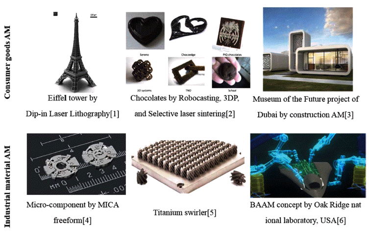
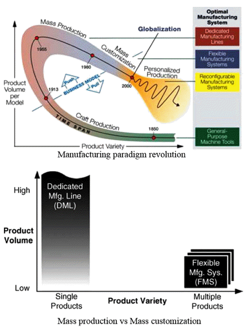
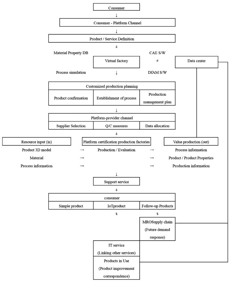
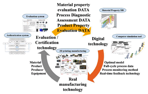

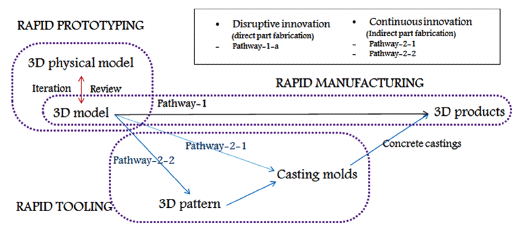
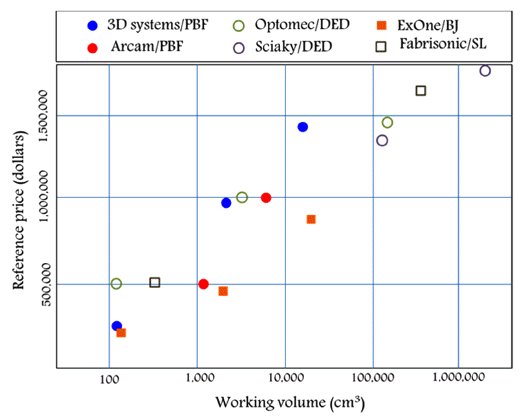

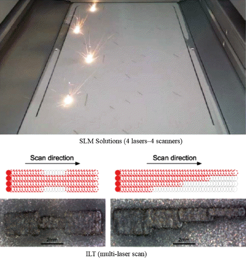

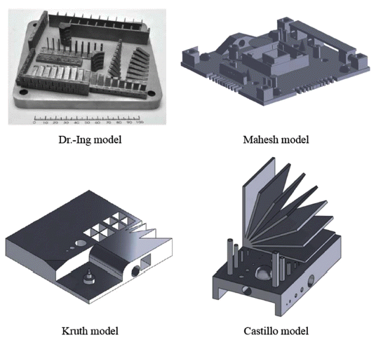
Fig. 1
Fig. 2
Fig. 3
Fig. 4
Fig. 5
Fig. 6
Fig. 7
Fig. 8
Fig. 9
Fig. 10
Fig. 11
| Additive Manufacturing (AM) | n―a process of joining materials to make objects from 3D model data, usually layer upon layer, as opposed to subtractive manufacturing methodologies. |
| Synonyms | additive fabrication, additive processes, additive techniques, additive layer manufacturing, layer manufacturing, and freeform fabrication. |
| System | Definition | Commercial technology* |
|---|---|---|
|
|
||
| Binder jetting | AM process technology group that selectively injects liquid binder material into powder material | BJ, IPP, 3DP |
| Directed energy deposition | AM process technology group in which materials are melted and additive by using high-density energy sources such as laser, electron beam, and plasma arc | EBDM, LENS, IFF, LPF, EBF3, SMD, DED |
| Material extrusion | AM process technology group in which material is extruded through a nozzle or the like and additive at a selected position | FDM |
| Material jetting | AM process technology group in which a additive material is sprayed in the form of droplets and additive at a selected position | MJ, IPP |
| Powder bed fusion | AM process technology which selectively dissolves by using thermal energy in arranged powder material | SLS, SLM, EBM, DMLS, SHS |
| Sheet lamination | AM process technology group that stacks sheet-shaped materials and commercializes them | LOM, UAM |
| Vat photopolymerization | AM process technology group which selectively cures a liquid photopolymer in a container using a light source | SL, DLP |
| Division | Hardening | Sintering | Melting-coagulation | Hydration reaction | Solid junction | ||||||||
|---|---|---|---|---|---|---|---|---|---|---|---|---|---|
|
|
|||||||||||||
| Polymer | VP | MJ | SL | PBF | ME | ||||||||
| Metal | BJ | ME | PBF | PBF | DED | SL | |||||||
| Ceramic | BJ | ME | SL | PBF | PBF | DED | ME | BJ | |||||
| BJ Commercialization | Introduction of market | Laboratory level | |||||||||||
| Division | Representative products and product types | ||
|---|---|---|---|
|
|
|||
| Polymer and polymer composites | product | Photocurable polymer | UV polymer |
| Thermoplastic polymer | PLA, ABS, HIPS, Nylon, PERR, PVA, TPE, TPC, PA | ||
| Functional polymer | Rubber like polymer, multi-color agent, binder | ||
| Polymer base composite material | Polymer-polymer, polymer-metal, polymer-ceramic composite materials | ||
| type | Liquid, wire (filament), granular (powder, pellet) | ||
| Metal and Metal composites | product | Metal powder | Ti and Ti alloys, Al alloys, Ni alloys, Fe alloys, precious metals, Cu alloys |
| Metal wire | |||
| Metal foil | |||
| type | Powder, wire, sheet | ||
| Ceramic and Ceramic composites | product | Structural ceramics | Al2O3, SiO2, ZrO2, WC, TiC, SiC, TiN |
| Function Ceramic | BaTiO3, PZT, TCO, ZnO | ||
| Bioceramic | HA, TCP, Bio-glass | ||
| Ceramic base composite material | Ceramic-ceramic, ceramic-carbon, ceramic-metal composite materials, cement / concrete | ||
| type | Powder, sheet, slurry | ||
| Product Design | Pre-AM | AM | |
|---|---|---|---|
| Division | Different manufacturing methods from existing manufacturing techniques (bottom-up) | Product characteristics - Pre-processing technology optimized for manufacturing process | Real-time diagnostics on the production process - Feedback active control |
| Summary | A series of development processes related to product development Structural analysis, functional analysis Optimization considering characteristics of AM manufacturing process | Technology linking design technology and lamination manufacturing technology File format that can be printed and CAM format optimization Development of specialized S / W by process technology and linkage of equipment | Minimize process uncertainty of simultaneous production of small batches. Real-time monitoring of key factors by process technology. Process diagnosis - Analysis - Generalization of feedback function |
| Trends | Enhancement of topology optimization process (degree of design freedom) Active use of lattice structure (product characteristics, process profit) Computer simulation engineering design maximizing the effect of bottom-up technology, utilization of natural simulation and Big DATA | STL file utilization and correctability G-code control specific to the characteristics of extended equipment Part fill, minimum support automatically generated program for on-demand production Deformation prediction, process variable influence prediction simulation | Process monitoring using various sensors S / W process DB including key variables and necessary for process diagnosis feedback S / W and integrated equipment S / W and cloud environment control S / W |
| Program | |||
| Commercial program | Existing commercial CAD program Scanning-based reverse engineering Program Existing programs such as structural analysis, flow analysis, thermal analysis | Materialize Integrated S / W Autodesk Integrated S / W (Netfabb, Within, Delcam) Web based S / W (3D slash, Additive Industries, etc.) | Sigma Lab Sciaky EOS |
| Division | PBF (powder) | DED (powder, wire) | BJ (powder) | SL (sheet) | |||||
|---|---|---|---|---|---|---|---|---|---|
|
|
|||||||||
| Metal equipment | Arcam | Sweden | Optomec | USA | ExOne | USA | Fabri-sonic | USA | |
| ConceptLaser | Germany | Sciaky | USA | Digital Metals | Sweden | ||||
| EOS | Germany | Trumpf | Germany | ||||||
| ReaLizer | Germany | InssTek | Korea | ||||||
| Renishaw | England | BeAM | France | ||||||
| Sisma | Italy | DMG Mori Seiki | Germany | ||||||
| SLM Solutions | Germany | RPM Innovations | USA | ||||||
| 3D Systems | USA | ||||||||
| Matsuura | Japan | ||||||||
| OPM Lab | Japan | ||||||||
| Metal powder | [OEM] | [OEM] | [OEM] | [OEM] | |||||
| Arcam | Sweden | ExOne | ExOne | USA | Fabri-sonic | USA | |||
| ConceptLaser | Germany | ||||||||
| EOS | Germany | ||||||||
| ReaLizer | Germany | ||||||||
| Renishaw | England | ||||||||
| Sisma | Italy | ||||||||
| SLM Solutions | Germany | ||||||||
| 3D Systems | USA | ||||||||
| Matsuura | Japan | ||||||||
| OPM Lab | Japan | ||||||||
| [OBM] | |||||||||
| [OBM] | [OBM] | Self-supply | |||||||
| LPW | England | LPW | England | Hoeganaes | Sweden | ||||
| Tekna | Canada | Praxair | USA | ||||||
| SMT | China | Carpenter | USA | ||||||
| AP&C | Canada | ATI | USA | ||||||
| Osaka Titanium Technologies Japan | Tekna | Canada | |||||||
| Hoeganaes | Sweden | SMT | China | ||||||
| Additive Metal Alloys | USA | ||||||||
| NanoSteels | USA | ||||||||
| Powder | Powder manufacturing process | AM process |
|---|---|---|
|
|
||
| Fe-C (graphite) | Tumbling mixing (0, 0.4, 0.8, 1.2, 1.6 wt.% C) | Selective laser sintering[19] |
| WC-Co | Granulation (4, 10 wt.% Co) | Selective laser sintering |
| Bronze infiltration[20] | ||
| Invar 36 (Fe-Ni)-TiC | Blended powder (30, 60, 80 wt.% TiC) | Direct metal laser sintering[21] |
| AA6061-Mg-Sn-Nylon | Blended powder (2 wt.% Mg, 1 wt.% Sn, 3 wt.% nylon) | Selective laser sintering |
| AA6061 infiltration[22] | ||
| Cu-Ti-C-Ni | Mixture (planetary ball milling) | Selective laser sintering |
| In-situ carburization[22] | ||
| Invar 36-TiC | Powder mixture (0, 6.6, 14.3, 22.1, 29.4, 52.1 vol.% TiC) | Direct laser deposition[23] |
| Fe-Nylon | Filament (30, 40 vol.% Fe) | Fused deposition modeling[24] |
| IN 625-TiC | Planetary ball mixing (5 wt.% TiC) | Laser metal deposition[25] |
| IN 625-Al2O3 | ||
| IN 625-SiC | Ball mixing (5 wt.% additives) | Laser powder bed fusion[22] |
| IM 625-TiC | ||
| AlSi10Mg-TiC | Ball mixing (5 wt.% TiC nanoparticle) | Selective laser melting[26] |
| Fe-Ti-C | Ball mixing (24.9 wt.% Ti, 5.1 wt.% C) | Laser additive manufacturing |
| (directed energy deposition)[22] | ||
| Issues in Materials | Issues in Fabrication | Issues in Certification |
|---|---|---|
|
|
||
Materials development Selectivity/AM-matched materials Cost-effectiveness Effects of material properties Reliability of materials Multi-functional materials |
Increasing building rate IncreHigher power/multi-lasers In-situ diagnostics & feedback Cost-effectiveness Changeover time reduction Enhanced precision Post-processing reduction |
AM part certification Industry accreditation Standard and specification Safety margins Characterizations/NDE included Linkage to conventional certif |
| Classification | Detailed classification | Summary | Features |
|---|---|---|---|
|
|
|||
| Powder | Sampling | A method of extracting a small sample from a mass- produced powder | Scoop sampling, Table sampling, Chute splitting, spin riffling, cone and quartering |
| Chemical composition | Bulk chemical composition | Sampling of more than a predetermined amount of powder through a standardized procedure and analyzing the representative chemical composition of the powder | ASTM E539, E572, E2371, E2465, E2594, E2626, E1447, E2792, E1569, E1941, E1019, E1131 |
| Surface analysis | Analysis of phases or adsorbates present on the surface of the powder | XPS AES FTIR etc. | |
| Physical Characteristics | Particle size distribution | A representative value of the size and size distribution of the powder is selected according to the standardized procedure | Sieving, Laser scattering, Gravitational sedimentation, Microscopy, Electro-zone sensing |
| morphology | The factor that defines the geometric properties of the powder is expressed as a numerical value | Elongation, sphericity, roundness, circularity | |
| Pore | Quantify the pores present in the powder | Microscopy, micro-CT | |
| Surface area | Measure the surface area of the powder | ASTM B92222-02 | |
| Hall flow | Evaluate fluidity through the time it takes for 50 g powder to pass through a nozzle of 25.4 mm diameter | ASTM B213 | |
| Flow rate | Carney flow | Evaluation of fluidity using Carney funnel diameter 50.8 mm | ASTM B964 |
| Angle of repose | Evaluation of particle-to-particle friction and flow characteristics by analyzing the physical shape (angle) of the powder pile in static and dynamic states | ISO4324:1977 | |
| Fill rate | Apparent density | Density is calculated by measuring the mass of the powder in the cup after sifting the powder into the density cup having a certain volume | ASTM B0212-99 |
| Tap density | Filling the powder into the cylinder to measure volume to mass | ASTM B527-93 | |
| Division | Deformation behavior | Fracture behavior | ||
|---|---|---|---|---|
|
|
||||
| Tension test, compression test, bearing test, modulus test, hardness test | Fatigue test, fracture toughness test, creep test | |||
|
|
||||
| Properties | Stress-Strain Diagram Torque-Twist Diagram Yield Strength Yield Point Tensile Strength Rupture Strength Upper Yield Strength Lower Yield Strength Compressive Strength Bearing Strength Ductility Young’s Modulus Shear Modulus Poisson’s Ratio Tangent |
Modulus Secant Modulus Chord Modulus Brinell Hardness Number Rockwell Hardness Number Knoop Hardness Number Vickers Hardness Number Scleroscope Hardness Number Webster Hardness Indentation Hardness Indentation Modulus Elasto-plastic Hardness |
Number of Cycles to Failure Stress/Strain Ranges Strain Ratio Fatigue Crack Growth Rates as a Function of Stress- Intensity Factor Range (ΔK) Fatigue Life Tensile and Compressive Stresses as a Function of Number of Fatigue Cycles Representative Cycles of Mechanical Strain Versus |
Stress/Temperature Plane-Strain Fracture Toughness Fracture Toughness Plain-Strain Crack-Arrest Fracture Toughness Crack-Tip Opening displacement Absorbed Impact Energy Specimen Residual Strength Creep Crack Growth Rate Threshold Stress Intensity Factor Crack Resistance Curve |
| Standard number | Standard name |
|---|---|
|
|
|
| ASTM F 2924-14 | Standard specification for additive manufacturing titanium-6aluminum-4vanadium with powder bed fusionc |
| ASTM F 3001-14 | Standard specification for additive manufacturing titanium-6aluminum-4vanadium ELI (extra low interstitial) with powder bed fusion |
| ASTM F 3055-14 | Standard specification for additive manufacturing nickel alloy (UNS N07718) with powder bed fusion |
| ASTM F 3056-14 | Standard specification for additive manufacturing nickel alloy (UNS N06625) with powder bed fusion |
Table 1
Table 2
Table 3
Table 4
Table 5
Table 6
Table 7
Table 8
Table 9
Table 10
Table 11
TOP
 KPMI
KPMI


 Cite this Article


