Warning: mkdir(): Permission denied in /home/virtual/lib/view_data.php on line 81

Warning: fopen(upload/ip_log/ip_log_2024-11.txt): failed to open stream: No such file or directory in /home/virtual/lib/view_data.php on line 83

Warning: fwrite() expects parameter 1 to be resource, boolean given in /home/virtual/lib/view_data.php on line 84
Research Trend of Additive Manufacturing Technology
Skip Navigation
Skip to contents

Journal of Powder Materials : Journal of Powder Materials

OPEN ACCESS
SEARCH
Search

Articles

Page Path
HOME > J Korean Powder Metall Inst > Volume 23(2); 2016 > Article
Review Article
Research Trend of Additive Manufacturing Technology
Hanshin Choi, Jong Min Byuna, Wonsik Lee, Su-Ryong Banga, Young Do Kima,*
Journal of Korean Powder Metallurgy Institute 2016;23(2):149-169.
DOI: https://doi.org/10.4150/KPMI.2016.23.2.149
Published online: March 31, 2016

Incheon Regional Division, Korea Institute of Industrial Technology, Incheon 21999, Korea

a Department of Materials Science & Engineering, Hanyang University, Seoul 04763, Korea

*Corresponding Author: Young Do Kim, +82-2-2220-0408, +82-2-2220-4231, ydkim1@hanyang.ac.kr
• Received: April 8, 2016   • Revised: April 17, 2016   • Accepted: April 20, 2016

© The Korean Powder Metallurgy Institute. All rights reserved

  • 508 Views
  • 3 Download
  • 4 Crossref
prev next
  • Additive manufacturing (AM) is defined as the manufacture of three-dimensional tangible products by additively consolidating two-dimensional patterns layer by layer. In this review, we introduce four fundamental conceptual pillars that support AM technology: the bottom-up manufacturing factor, computer-aided manufacturing factor, distributed manufacturing factor, and eliminated manufacturing factor. All the conceptual factors work together; however, business strategy and technology optimization will vary according to the main factor that we emphasize. In parallel to the manufacturing paradigm shift toward mass personalization, manufacturing industrial ecology evolves to achieve competitiveness in economics of scope. AM technology is indeed a potent candidate manufacturing technology for satisfying volatile and customized markets. From the viewpoint of the innovation technology adoption cycle, various pros and cons of AM technology themselves prove that it is an innovative technology, in particular a disruptive innovation in manufacturing technology, as powder technology was when ingot metallurgy was dominant. Chasms related to the AM technology adoption cycle and efforts to cross the chasms are considered.
Manufacturing engineering has supported industrialized society by making things in effective ways and it has been persistently innovated to satisfy contemporary normal. We can get insights on the past, present, and future of manufacturing technology from The Global Manufacturing Revolution by Korean [1]. He pointed out that manufacturing paradigm has been changed from craft production to mass production, mass customization, and personalized production in order and manufacturing technology is responsive to the paradigm shift of market and society. Ford manufacturing system and computer numerical control system are emphasized to make big changes in manufacturing paradigm in the past. With aids of computer engineering and information technology, pivotal changes in manufacturing hierarchy and business models are currently occurring. As a matter of fact, the division between producers and customers and also boundary between production and service become ambiguous as interactive fusion between manufacturing technology and communication technology proceed. With respects to product variety, markets push manufacturing engineering to meet diversified customers’ individual interests at low production volume. Current centralized production and distribution system cannot fulfill the socalled mass personalization paradigm. Moreover, current dominating manufacturing technology cannot satisfy volatile markets. As a result, innovative manufacturing technology is required. On the other hand, manufacturing technology should be compatible to decoupling between economic growth and environmental sustainability. It can be achieved by reducing emissions with maximized materials utilization and energy efficiency in making things. In these contexts, mass customization and sustainable manufacturing are recent new normal for advanced manufacturing technology.
Additive manufacturing has drawn attentions. What we think is manufactured as tangible 3D thing when we need and where we want by ourselves like building Lego blocks. Most of us are well accustomed for 2 dimensional printing. Basically, additive manufacturing technology is analogous to 2D printing and it is the reason why 3D printing technology is an easy terminology to understand additive manufacturing. To print 2D something out, one should firstly prepare a file via computer programs, scanner, camera, and so on. After that, the file is transferred to a printer through conversion to relevant print file formats. 2D information is translated on paper, cloth, even metal foil by line-by-line fashion. Printing conditions are selected by considering speed, cost, and quality. In order to print tangible 3 dimensional products, add z-axis to 2D printing. Additionally, 2D printing technology and business models give us sights on the future of 3D printing. Improved resolution of printed things, enlarged design selectivity, and cost-effective production are solved and they are coupled with IT business solutions by which customers have no difficulties in accessibility, security, transactions, and so on. Standardization (substrate size and ink), bait & hook business model (printer-cartridge relation), online printing-delivery services, and printable electronics of 2D printing are also good keywords for 3D printing.
What makes recent additive manufacturing be at the center of manufacturing technology issues is that it can change fundamentals of manufacturing technology with satisfying the new normal. Pros and cons on additive manufacturing prove that AM is the innovation technology and it suffers from chasm in innovation technology adoption cycle. A great numbers of journal papers and articles are being published and they cover whole ranges of AM from process optimization methodologies to successful industrial adoption stories.
In the present literature, we surveyed literatures, comments, reports, and websites and four conceptual attributors which build Additive Manufacturing Technology were derived to be helpful for new entrant to get an insight on additive manufacturing. In addition, chasm triggering factors were considered and efforts to cross the chasm are shortly introduced.
Additive manufacturing is defined as processes of joining materials to make objects from 3D model data, usually layer by layer, as opposed to subtractive manufacturing technology in ASTM F 2792-12a [2]. Macroscopically, AM technology is divided into three stages in process flow: pre-AM, AM, and post-AM.
2.1 Pre-AM
Pre-AM covers 3D model generation, conversion to printing formats, support generation, products packing in a certain volume, and simulation of AM processing. 3D models can be generated by genuine computer aided design tools [3-5] or reverse engineering tools [6-8] such 3D scanner, 3D tomography, and set of multiple cameras. In addition, augmented reality is utilized to model generation with facility [9]. Furthermore, lattice structures [10] and bio-inspired models [11] are vigorously utilized for complex model generation. Before AM, 3D models should be converted to printable formats such as STL (standard tessellation language), AMF (additive manufacturing file), and modified AMF which can be read by computer aided manufacturing system [12]. Reconstructed 3D model after 2D slicing has some limitation in replicate original smooth contoured 3D model. In the literature [13], effects of processing steps on sensitivity of geometric deviation from 3D model generation to as-built product are quantified and errors from model generation strategy are emphasized in particular for medical application. Support is intentionally added to 3D model in order to mechanically support overhang structures during layer-by-layer fabrication and/or manage thermal distortion [14]. Basically, support structure needs to minimize and it is easy to be removed from the viewpoint of material utilization, process savings, and productivity [15]. How to arrange multiple products in a certain volume of working chamber is a practical issue especially for process efficiency and cost reduction. Genetic algorithm, heuristic approach [16], and arc flow model [17] are suggested to solve the so-called bin packing problem. Furthermore, a modified group technology and grey clustering are assessed as methodology for production plan of multiple products manufacturing [18]. So many parameters affect product qualities, cost, and productivity directly or indirectly and therefore, it is not practical to empirically quantify all the process parameters effects. In this context, rehearsal before starting AM helps us to select optimum AM strategy. Simulation covers powder bed packing for powder bed based AM, inflight particle trajectory during directed energy deposition AM, feedstock-energy source interactions, thermal cycles, phase transformations, stress/strain development, and so on. It helps us to understand complex phenomena which are hard to investigate and to monitor process governing parameters.
2.2 AM
3D products are manufactured by consolidating 2D patterns layer-by-layer. Additive manufacturing technology is supported by materials, machines, and process optimization. In the case of materials, polymers, metals, ceramics, and composites are used and feedstock can be solid, liquid, gas, and mixture of them. When it comes to machines, they have different consolidation mechanisms such as photo-polymerization, melting-solidification, vaporization- condensation, extrusion, liquid phase sintering, bonding, and joining. According to consolidation principle, AM machine system is quite different. Lots of AM processes have been introduced and commercialized until now. AM technology is well classified to 7 groups in ASTM according to main principles. They are binder jetting AM, directed energy deposition AM, materials extrusion AM, materials jetting AM, powder bed fusion AM, sheet lamination AM, and vat photo-polymerization AM. Characteristics of the AM groups and commercial processes are summarized in Table 1.
Table 1.

Characteristics and commercial processes of each AM group in ASTM standard

Standardgroup Characteristics Materials

Materials Consolidation mechanism Polymer Metal Ceramic Composite

Binder jetting Powders Binders Polymerization O O O O
Directed energy deposition Powders Wires Melting-solidification O O O O
Material extrusion Wires Extrusion-polymerization O O O O
Material jetting Photopolymer Wax Photopolymerization O O O
Powder bed fusion Powders Melting-solidification O O O O
Solid/liquid phase sintering
Sheet lamination Sheets Wires Bonding Joining/welding O O O
Vat Photo-polymerization Photo-polymers Photopolymerization O O O
  • Binder jetting AM [19-23]: 2D pattern is fabricated by dropping binder on the pre-placed powder bed. 3D primitive part is consolidated by polymerized binder which was infiltrated into powder bed. Polymers, metals, ceramics, and composites are built.

  • Directed energy deposition AM [24-28]: Wire or powder feedstock is fed into molten pool which is generated by high energy density heat sources such as laser, e-beam, and plasma transferred arc. Meltingsolidification is the main consolidation mechanism. Because feedstock is in-situ fed into local molten pool, chamber is not imperative. Metals are usually used.

  • Materials extrusion AM [29-33]: Feedstock materials such as thermoplastic filament or polymer bearing composite feedstock are extruded and placed on demand. Polymerization hardens the deposit.

  • Materials jetting AM [34-38]: Photopolymers are jetted and in-situ cured by light sources.

  • Powder bed fusion AM [39-43]: Laser or e-beam is irradiated on pre-placed powder bed and solidification of molten pool results in consolidation. Another powder layer is placed on the previous patterned layer.

  • Sheet lamination AM [44-48]: Sheet is placed and bonded to previous layer. 2D pattern is translated on the bonded sheet by knife or laser.

  • Vat photo-polymerization AM [49-53]: Liquid photopolymer is contained in a specific vat and it is hardened by light irradiation. Working plate is immersed into liquid photopolymer at pre-set depth after 2D patterning.

Feedstock material can be another criterion for classification of additive manufacturing (Table 2). Polymers, metals, ceramics, and composites are used to make 3D products. Among them, composites are multi-components systems that contain different reinforcement phase from matrix. Composites are divided into polymer matrix composites, metal matrix composites, and ceramic matrix composites according to matrix materials. Reinforcement phases are of particulates, fibers, and platelets according to morphology. Thermoplastics polymers are generally built by material extrusion AM such as fused deposition modeling. Vat photo-polymerization and material jetting AMs use photopolymers. Other thermoset polymers are used for powder bed fusion AM. Lots of researches have been conducted to expand functionalities of feedstock materials such as high strength, rubber-like feeling, full coloration, humidity resistance, and conductivity. In addition, environmental inertness such as bio-degradable and recyclable materials as well as cost reduction needs to improve. Polymer matrix composites are alternative ways to build high performance structural components. Ceramic additive manufacturing technology is extensively explored. Binder jetting AM, powder bed AM, material extrusion AM, and sheet lamination AM are representative topics. ZrO2 and Al2O3 are typical structural ceramics and their applications for complex 3D products are studied by AM. Powder bed fusion AM of binder coated ceramic powder, for example, selective laser sintering of PP (polypropylene) coated Al2O3, is utilized to fabricate green body. Post-processing and sintering are followed [54]. Dielectric ceramics and piezoelectric ceramics are used for functional ceramic AM. Binder jetting AM and sintering of BaTiO3 powder for piezoelectric sensor is explored [55]. Bio-ceramic AM and hybrid AM [56] use hydroxyapatite, tricalcium phosphate, and bio-glass materials. Metals and metal composites feedstock are reviewed in the next chapter.
Table 2.

Additive manufacturing materials

Divisionc Polymers Metals Ceramics Composites

AM materials Thermoplastics
Thermosets
Photopolymers
Elastomers
Powders
Wires
Sheets
Structural ceramics
Functional ceramics
Bio-ceramics
PMC
MMC
CMC
AM technology can be classified in other ways according to other criteria such as feeding fashion, feedstock characteristics, and consolidation mechanism in order to get insights on architecture of AM technology, selection of AM technology, and future development of AM technology.
2.2.1

Feeding manner

In the case of feeding fashion, feedstock materials are pre-placed before patterning or they are in-situ fed during pattering. Feeding fashion determines AM machines and also it affects AM strategy and product design. In particular, possibility for applications of multiple materials is dependent on feeding manner. Powder bed fusion, vat photo-polymerization, and binder jetting AMs adopt pre-placed feedstock and therefore, they have limitations in multiple materials utilization for a component manufacturing. Such limitations to monolithic materials are originated because unused materials have be reused. On the other hand, multiple feedstock can be fed simultaneously or alternately for directed energy deposition, material jetting, and material extrusion. Sheet lamination is unique that sheet feedstock is pre-placed before patterning but it does not require any vat or chamber. Different kinds of sheet materials can be cladded alternately. Dimension of 3D product is also largely related to feeding manner. AM with pre-placed feedstock needs chamber or vat and therefore, products size are limited by chamber/vat volume.
2.2.2

Feedstock characteristics

Though gas and slurry are used for AM, feedstock materials are generally solid, liquid, and suspension. Photopolymer feedstock for vat photo-polymerization and material jetting is liquid and in some cases particulates are intentionally dispersed in the feedstock. In the case of solid feedstock, they are divided into powder, wire, and sheet. Powders are used for powder bed fusion, binder jetting, and directed energy deposition. On the other hand, wire-like filament is feedstock for fused deposition modeling and metallic wires are used for directed energy deposition AM. Paper, wood, and metal foils are used for sheet lamination AM. Materials share high fraction of cost-structure in AM and it is proportional to product number. Though recent prices of AM materials are over- estimated by small market size and current AM market segmentation, feedstock price and material utilization are quite different according to feedstock characteristics. For example, AM grade Ti-6Al-4V powder is $77/lb and 1.6 mm thick wire is $50/lb [55].
2.2.3

Consolidation mechanism

Polymers, metals, and ceramics are of different materials properties and accordingly, AM technology is differentiated owing to different consolidation mechanism of each feedstock material. Polymers are hardened to form bulk structures by chemical, thermal, and photo polymerization reactions [56]. In material extrusion, thermoplastic filament is fed into nozzle and then it is heated and extruded in nozzle. After that, deposit is hardened on the surface of previously deposited layer. On the other hand, solid-state consolidation or consolidation by binder is utilized for ceramics [57]. Ceramic primitive is further processed to final product manufacturing. Melting and solidification are typical consolidation routes to form 3D metallic components while solid-state sintering and ultrasonic welding is possible.
2.3 Post-AM
At the current state of AM technology, supported product, geometric clearance, surface quality, microstructures, defects, and residual stress of as-built products do not satisfy customers’ specifications. Therefore, post-AM processes are requisite and they range from separation of as-built products to final products. Post-AM is closely related to market, AM process, and AM strategy. In the case of industrial components, post-AM is mandatory and the as-built products undergo support removal, powder removal, annealing, densification, infiltration, machining, polishing, coating, and so on. Post-AM is optionally selected according to properties of as-built products. Supports and plates are detached from as-built products by chemical dissolution, mechanical cutting, or electro-discharge machining. After powder based AM processes, forced air jetting or aerosol blasting with same powders with product is conducted to remove and reuses unused powders. Qualities of as-built product are usually compensated by productivity. As a matter of fact, higher resolution AM process results in near-net shaped or net shaped products during substantial manufacturing time. With respect to dimensional accuracy, as-built products are inherently or intentionally larger than final products and accordingly, removal of unnecessary mass is required. Fig. 1 shows a representative example of Ti armored plate by Norsk Titanium. Semi-final product is produced by wire plasma arc process which belongs to directed energy deposition AM and deposition rate reaches 10 kg/hr. In spite of fast building speed, dimensional accuracy is far deviated from final product. Significant mass need to be machined during post-AM process. The example gives us an important insight on manufacturing plan on the basis of current state of AM technology. During whole life manufacturing cycle, collaboration of AM and post-AM enlarges manufacturing plan in reality.
Fig. 1

Example of post-processing of directed energy deposition AM product.

KPMI-23-149_F1.gif
Densification of as-built products is conducted by infiltrations or post thermal/thermos-mechanical treatments. Infiltration of as-built primitives with secondary phases is common for binder jetting AM and selective laser sintering. On the other hand, annealing thermal cycle or hot isostatic pressing is subsequent for stress relief, full densification, and microstructure modification after powder bed fusion metal AM. In the case of vat photopolyemerization AM and material jetting AM, UV curing is generally followed to harden the AM products.
Surface quality such as surface roughness is not so good because of stair-step effects and resolutions of AM technology. External surface can be polished by conventional methods such as mechanical polishing, chemical/ electrochemical polishing, vibrational polishing, and blasting. However, internal surfaces of complex products are difficult to polish. It is chemically or electrochemically smoothened. In the case of Ti-6Al-4V open structured product [58], combined post-processing strategy is suggested to improve surface roughness and homogeneity. Chemical etching is effective for removing tangled powders and subsequent electrochemical polishing results in homogeneously smoothened struts. Otherwise, abrasive flow machining is effective. During abrasive flow machining (AFM), polishing suspension containing abrasive media such as SiC, Al2O3, diamond, WC particles flow through porous products and internal surface is smoothened by collision of abrasive particles. Numerical CFD simulation for AM is explored in the literature [59]. On the other hand, dry-ice blasting is exploited to clean complex AM products [60]. CO2 snow (dry ice particle) from CO2 is blasted to surface of AM product. Cryogenic effects, mechanical impact, and phase transformation of CO2 particles make surface smooth [61].
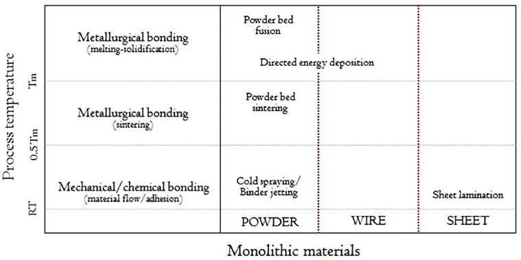
In this chapter, we briefly overview metal additive manufacturing. Technology and business model of metal AM are quite different from polymer AM. Powder bed fusion AM, directed energy deposition AM, binder jetting AM, and sheet lamination AM are commercialized. As shown in Fig. 2, process temperature and feedstock are different according to AM processes. Pre-placed metal foil is bonded to previous patterned layer via ultrasonic welding. Vibrational energy imparts friction at interface and solid-state mechanical bonding is achieved [62]. After bonding, 2 dimensional pattern is obtained by laser cutting process. One of advantages of metal sheet lamination AM is to build composite products such as multi-layer architecture and wire embedded architecture. Metallic wires are used for directed energy deposition AM. Wire feedstock is externally fed into molten pool which is locally generated by high energy density energies such as laser, electron beam, and transferred arc. Multiple wires are utilized simultaneously or alternately. Consolidation mechanism is diversified for powder based metal AM. Melting and solidification for both powder bed fusion AM and directed energy deposition AM. Solid-state consolidation via solid state sintering or liquid phase sintering is also achieved for powder bed AM. In the case of binder jetting AM, powders do not suffer from thermal cycle but they are bound together by externally dropped adhesive binder. As-built products from melting and solidification route result in full density or near-full density and however, thermal distortion, defective microstructures, and anisotropic microstructures need to be cautiously manipulated.
Fig. 2

Metal additive manufacturing process according to feedstock dimension and process temperature.

KPMI-23-149_F2.gif
Solid state consolidation of powder bed AM is divided into solid state sintering and liquid phase sintering. Selective laser sintering and hot isotropic pressing are good examples for the solid state sintering [63]. A variety of binary powder systems of base metal powder and lower melting point additive are used for liquid phase sintering [64]. During laser irradiation cycle, melting, spreading, and solidification of lower melting point result in consolidation of base metal powder in the same manner to the conventional liquid phase sintering. However, time constraint within several micro-seconds is considered for AM technology. Otherwise, porous structured AM primitives are filled with lower melting point secondary phase by post pressureless or pressurized infiltration process. In the case of Al/AlN composite fabrication, binder burnout and nitriding of SLS primitive precede molten Al infiltration. Binder jetting metal AM utilizes solid state consolidation. Binder is dropped on the surface of preplaced powders in powder bed and it infiltrates toward powders. Polymerization of binder consolidates powders. In the most cases, binder jetting AM primitives undergo same post-processing with metal powder injected green body: binder burn-out and sintering. In Table 3, characteristics of representative metal AM processes are compared. Full density 3D products are generally manufactured by the processes except for binder jetting AM. It still takes a substantial processing time to build products and further improvement for as-built product properties is required.
Table 3.

Comparison of metal additive manufacturing processes [65]

ASTM classification Commercialized process (Maker) Process time* Properties

Relative density (%) Accuracy (mm) Surface roughness (Ra/um)

Binder jetting Digital part materialization (ExOne) 10 hours** > 95*** ~ +/- 2.0 ~ 9
Powder bed fusion Electron beam melting (Arcam AB) 12 hours > 99 ~ +/- 0.2 ~ 20
Directed metal laser sintering (EOS) Laser engineered net shaping (Optomec) 24 hours > 99 ~ +/- 0.05 ~ 9
Directed energy deposition Ultrasonic additive manufacturing 10 hours > 99 ~ +/- 0.125 ~ 25
Sheet lamination (Fabrisonic LLC) 24 hours > 99 ~+/- 0.015 ~ 7

*Process time: time generally required for making 125×125×125 mm3 cube product

**Time for primitive product by binder jetting AM excluding post-processing (debinding and sintering)

***Relative density after sintering

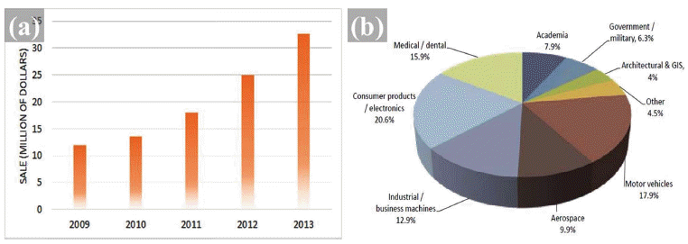
Market size of AM metal materials is still so small though vigorous growth is observed in Fig. 3. This is mainly due to immaturity of AM technology, high prices of metal AM machines, risk for large capital investment, and lack of materials selectivity. Bio-devices, aerospace components, and molds are current leading markets because AM can achieve full personalization for patients and weight reduction and design complexity of low-volume customized markets. Metal powders are widely used for metal AM while various wires and sheets are commercially available. Commercialized metal AM powders and suppliers are summarized in Table 4.
Table 4.

Metal powders and suppliers

Applications Metal powders Powder suppliers

Medical devices
Aerospace components
Molds
Automotives
Energy
Custom/jewelry
Others
Pure Ti/Ti-6Al-4V
Co alloys
(CoCr, CoCrMo)
Al alloys
(AlSi, AlSiMg, AlMgSc, 7XXX)
Ni alloys
(IN 625, IN 718)
Fe alloys
(316L STS, Maraging, 17-4 PH)
LPW Technology Ltd
Sandvik Materials Technology
H ganas AB
Carpenter Technology Corp.
Allegheny Technologies Incorporated
H.S. Starck
Additive Metal Alloys
Advanced Powders & coatings
CSIRO
Nanosteel
Cooksongold
Fig. 3

Metal markets and market share of metal additive manufacturing; (a) Metal markets (b) Market share of metal AM.

KPMI-23-149_F3.gif
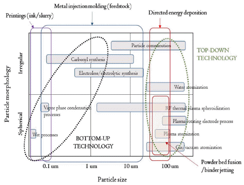
Metal powders can be produced by various different processes and their morphologies and sizes are largely dependent on manufacturing principles. Powder production technology can be divided into two groups as summarized in Fig. 4: bottom-up technology and top-down technology. Carbonyl process belongs to bottom-up technology because solid powders are produced from condensation of vapor species. To the contrary, atomization processes such as water atomization, gas atomization, and centrifugal atomization are top-down technology because solid particles are produced from molten liquid. Generally, several decades of micro-meter powders with spherical morphology are used for AM technology. With respect to metal powder market, values are divided into high quality powders and low price powders according to AM product requirements. Quality is the primary requisite for aerospace components. Therefore, plasma atomization process, plasma rotating electrode process, and plasma spheroidization process compete with conventional gas atomization process. To the contrary, lower cost can promote metal AM to penetrate high volume production market.
Fig. 4

Ti and Ti alloy prices according to powder preparation method (price range results from chemical composition).

KPMI-23-149_F4.gif
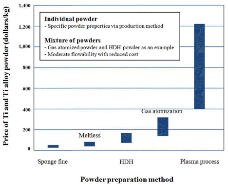
Titanium is a representative metal for current AM. Ti powder characteristics are quite different according to production method as summarized in Table 5. Spherical Ti powders are generally produced by gas atomization, plasma atomization, and plasma rotating electrode process. On the other hand, applicability of low price Ti powders is being intensively assessed. Fig. 5 shows powder prices according to powder production processes.
Table 5.

Comparison of Ti powders from different production processes

Powder production process Morphology Size (median/um) Impurities Reference

O C

Kroll (sponge fine) Irregular/facet 180-800 0.35 0.05 66
Hunter (sponge fine) Irregular/facet 180-800 0.35 0.05 67
FFC Cambridge (crushed powder) Irregular/facet 0.40 68
HDH powder Irregular/facet 38 0.25 0.04 66
Gas atomization Spherical 32 0.15 0.03 69
Plasma rotating electrode process Spherical 130 0.15 0.02 70
Plasma atomization Spherical 60 0.15 0.04 71
Fig. 5

Ti and Ti alloy prices according to powder preparation method (price range results from chemical composition).

KPMI-23-149_F5.gif
In metal powder AM, powders are pre-placed before building in chamber or they are coaxially fed into molten pools in directed energy deposition AM. Otherwise, kinetic spraying of metal powders is used to build preform. In the powder bed fusion additive manufacturing processes, powder materials are layered at a certain thickness and then 2-dimensional pattern is directly translated on the pre-placed powder bed. Repetition of powder layering and 2-D patterning results in 3-D product development. Therefore, pre-placed powder layer thickness, powder packing density, and uniformity are critical for powder bed based AMs. Effects of powder properties on dimensional accuracy and surface finish of as-built AM products are extensively investigated. Powder layer thickness and packing density are determined by powder size and morphology. Relation among powder size, number of powder layer, and molten bead thickness can be estimated from the Eq. (1) which is originally applied for sintering [68].
(1)
d=δ0.7×n×(1α)1/3×(1p)1/3
where d is particle diameter, δ is sintered layer thickness (overlay thickness here), n is number of particle layer, (1- α) is packing ratio, and p is porosity. In a randomly packed mono-dispersed spherical powder bed, particle diameter is proportional to target overlay thickness and it is inversely proportional to number of powder layer in newly overlaid powder bed. It means that powder size and particle layer number should be considered in selecting thickness of molten bead. Accordingly, thinner layer thickness can be allowed by randomly closed packed fine powders. It results in mitigation of stair-step effect and sufficient remelting of underlying defects [66]. Accordingly, full density AM body with quality surface can be manufactured. However, particle interaction is enhanced as particle size reduces. It deteriorates powder flowability and packing density. Particle friction is also affected by morphologies such as sphericity, roundness, and so on. As a result, powder characteristics are regarded as crucial factors affecting AM processing ability and AM product properties (Table 6). On the other hand, directed energy deposition AM is not so sensitive to powder morphology [69, 70] though in-flight particle properties are affected by powder morphology [71]. However, it is note that internal porosity of powder affects porosity and properties of as-built product. By comparing gas atomized powder with internal pore and plasma rotating electrode processed powder in directed energy deposition AM, it is proven that residual pore from gas atomized IN 718 deteriorates mechanical properties. It is also confirmed for Ti-6Al-4V powders.
Table 6.

Example Powders and Characteristics by Various Processes [72]

Powder Process Shape D50, μm Distribution Flow time, S Cost

Al gas atomized spherical 30 moderate nf moderate
Co alloy gas atomized spherical 90 -
Fe gas atomized spherical 66 9
stainless gas atomized spherical 12 3.8
TiAl gas atomized spherical 180 30

Cu water atomized nodular 62 wide 48 low
Fe water atomized irregular 75 26
Pb water atomized ligamental 42 24
stainless water atomized irregular 60 2.6
tool steel water atomized nodular 70 50

Fe Centrifugal spherical 75 moderate 14 high
Ti alloy Centrifugal spherical 175 28

*nf: Non-flow

Metal powder AM processes are popular and process features of some commercialized processes are compared in Table 7. Powder bed fusion AM shows higher resolutions than directed energy deposition AM (compare beam size and layer thickness) but product dimension is limited by chamber volume.
Table 7.

Features of commercialized processes in Metal powder AM processes

Division Unit Selective laser melting Electron beam melting Laser metal deposition Selective laser sintering

Equipment SLM 280HL (SLM Solutions) Arcam A2 (Arcam) Trumpf HLD 3504 (Trumpf) EOSINT M270 (EOS)
Build volume mm3 280×280×350 250×250×400 250×250×215
Beam size, in general um ~120 ~500 ~4100 ~500
Scanning speed in general mm/s ~800 ~800 ~40 ~100
Atmosphere Inert gas Vacuum Ar shielding gas Inert environment
Layer thickness um ~75 ~100 ~400 ~100
Feedstock um Powder (~50) Powder (~150) Powder (~200) Powder (~74)
ASTM group Powder bed fusion Directed energy deposition Powder bed fusion
In addition to pure metals and alloys, materials for metal AM are extended toward metal matrix composites. Composite 3D products can be fabricated by using composite feedstock materials, in-situ composite fabrications during building, or ex-situ compositing by post-AM processing. Composite feedstock is prepared by simple blending, mechanical alloying, or coating technology as exemplified in Table 8. Products are fabricated from the prepared powders by powder bed fusion AM. Otherwise, multiple powders are fed into molten pool through multiple feeding nozzles or functionally gradient structures are manufactured with changing feedstock materials during direct energy deposition AM. On the other hand, NiTi fiber embedded AA 6061 is fabricated by alternate layering of fiber placement and sheet lamination in metal sheet lamination AM. Infiltration of porous primitives by either powder bed fusion or binder jetting AM with lower melting point melts is well established to ex-situ compositing [71].
Table 8.

Example studies of metal matrix compoite AM

Powder Powder preparation AM process Ref.

Fe-C (graphite) Tumbling mixing (0, 0.4, 0.8, 1.2, 1.6 wt.% C) Selective laser sintering 72
WC-Co Granulation (4, 10 wt.% Co) Selective laser sintering Bronze infiltration 73
Invar 36 (Fe-Ni)-TiC Blended powder (30, 60, 80 wt.% TiC) Direct metal laser sintering 74
AA6061-Mg-Sn-Nylon Blended powder (2 wt.% Mg, 1 wt.% Sn, 3 wt.% nylon) Selective laser sintering AA6061 infiltration 75
Cu-Ti-C-Ni Mixture (planetary ball milling) Selective laser sintering In-situ carburization 76
Invar 36-TiC Powder mixture (0, 6.6, 14.3, 22.1, 29.4, 52.1 vol.% TiC) Direct laser deposition 77
Fe-Nylon Filament (30, 40 vol.% Fe) Fused deposition modeling 78
IN 625-TiC Planetary ball mixing (5 wt.% TiC) Laser metal deposition 79
IN 625-Al2O3
IN 625-SiC
IM 625-TiC
Ball mixing (5 wt.% additives) Laser powder bed fusion 80
AlSi10Mg-TiC Ball mixing (5 wt.% TiC nanoparticle) Selective laser melting 81
Fe-Ti-C Ball mixing (24.9 wt.% Ti, 5.1 wt.% C) Laser additive manufacturing (directed energy deposition) 82
Additive manufacturing is described with fundamental conceptual factors in an additive fashion as defined in Eq. (2): A is additive manufacturing, B is bottom-up manufacturing, C is computer aided manufacturing, D is distributed manufacturing, and E is eliminated manufacturing. It will help us to understand AM technology. Details for each factor are explained as follows and we consider how the four fundamental concepts work.
(2)
A=B+C+D+E
4.1 Bottom-up manufacturing
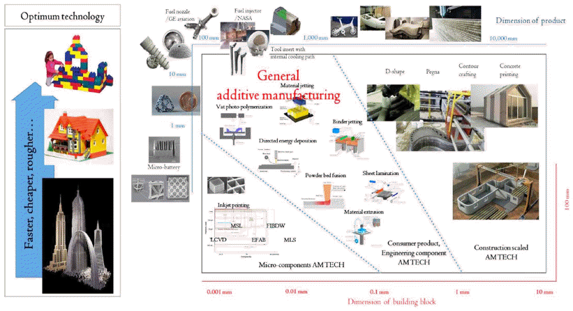
For convenience, top-down and bottom-up are widely used to describe dimensional change from raw material to product. Top-down manufacturing means that smaller products are produced from large material by subtracting unnecessary parts of the raw materials as the conventional subtractive manufacturing (SM) is. To the contrary, large products are manufactured from smaller raw materials in bottom-up manufacturing. From the definition of additive manufacturing, layer-by-layer manufacturing means that bottom-up manufacturing is a fundamental concept for additive manufacturing. Fig. 6 shows hierarchy of additive manufacturing from dimensional aspects. AM is arbitrarily classified to micro-AM, macro-AM, and general AM. The former micro-AM and macro-AM are extensively studied for micro-components fabrication and constructions, respectively. There is no standard criteria to define micro additive manufacturing. In the literature [83], Vaezi et al. classifies 3D micro-additive manufacturing technologies into three groups: scalable additive manufacturing, 3D direct writing, and hybrid processes. Extension of general AM toward micro-scale 3D manufacturing is regarded as the scalable micro-AM group. On the other hand, 3D direct writing technologies add z axis to wellestablished 2 dimensional direct writing technology though it is quite different technology. Third class of hybrid technologies are composed of additive deposition and subtractive removal sequentially. On the other hand, construction AM is well known and classified to macro-AM. Pegna, Contour Crafting, Concrete Printing, D-Shape and others are suggested to build large sized products layer-by-layer. Characteristics of the macro-AM processes are well reviewed in the literature and construction AM is mainly based on extrusion and 3d printing [84]. Design freedom, construction time reduction, labor safety, and cost reduction are promoters for AM technology in construction. In large sized engineering products manufacturing, CAD-to- SYSTEM strategy is explored by collaboration of multiple AM machines [85]. Regardless of AM technologies and consolidation principles, it is demonstrated that bottom- up manufacturing is simple but fundamental concept for additive manufacturing. Bottom-up manufacturing concept is partially described by Lego block. Finer building block allows finer products with higher dimensional accuracy and however, it requires much time and cost. It is emphasized that dimension of building block and building strategy are cautiously considered during product manufacturing plan.
Fig. 6

Micro-components AM technology, general AM technology, and construction scaled AM.

KPMI-23-149_F6.gif
4.2 Computer aided manufacturing
Computer aided manufacturing technology has a pivotal change through history of manufacturing. Computer numerical control (CNC) is prevailing on machining components and more complex designed products become available. Nevertheless, there are limitations in design selectivity from both engineering and economic aspects. Internal curved small cavity is impossible to obtain just by machining. When computer aided manufacturing is coupled with bottom- up technology, design complex is enormously enlarged and it is implicated by so-called Design-to-Performance. As a matter of fact, porous structures, lattice structures, and even bio-inspired designs are available in particular for medical devices, aerospace components, and design components thank to computer aided manufacturing concept. Moreover, multiple products with different design are simultaneously manufactured. Whole life-cycle of additive manufacturing from product design to product building depends on computer aided manufacturing concept. 3 dimensional model is obtained from CAD or reverse engineering. Model is modified by simulation of structural and functional properties from substantial iterations of different combinations of materials and structures using computers. Conversion to CAM language and revision of reconstructed printing model are preceded. With respects to AM processing, lots of process parameters and layering strategies affect and as-built product properties. Pre-simulation and closed-loop diagnosticsfeedback system are available to improve dependability of AM technology. In fact, studies on in-situ monitoring and acquisition of melt pool information such as melt pool geometry and temperature and direct feedback to system controller are intensively conducted [86]. Additional function of computing on AM technology is to allocate demanding products: grouping products, working chamber packing, manufacturing scheduling, and logistics. It means that knowledge of materials selection, model generation, process optimization, manufacturing planning, and business management is digitalized and immersed into manufacturing system. Ultimately, full automations of AM processes and sleepless factories are pursued and it is originated in computer aided manufacturing concept.
4.3 Distributed manufacturing
Materials and products flows in global economics are analogous to electrical grid. Conventional electrical grid shows a centralized generation and distribution. In this centralized generation, electricity is always supplied whether we want to use or not. From the supplier side, excess electricity generation capacity should be sustained to satisfy peak electricity demands. At the distribution stage, substantial energy is consumed during long-distance distribution of electricity. To the contrary, recent smart grid enables decentralized production of electricity with aids of renewable energy generation technology and interactive grid technology [87]. So-called procumers take parts in smart grid. One can buy centrally generated electricity and reversely one can sell one’s own generated electricity. To the extreme, bottom-level house grid may be detached from top level grid if renewable energy system becomes cost-effective and reliable. In the future, mass customization and/or personalization markets, additive manufacturing technology will play a crucial role as distributed renewable energy generation technology does in smart grid system. Interestingly, globalized economics depends on centralized production and world-wide distribution. Harsh market competition, particularly for economics- of-scale products, makes supply overwhelm demand. It implies that excess products are produced and delivered to markets with intensive resources consumption and huge environmental burdens through whole life-cycle of products. Distributed manufacturing concept of AM has advantages on the conventional centralized production. As a matter of fact, global procumers have already appeared in consumer AM markets with full exploits of long-tail economics based on interactive internets and delivery systems. Prevalence of matured AM technology will make global materials and products flows different from current centralized mass production system from the viewpoints of space and time. Firstly for space, we will just select what we want on borderless web but the products will be manufactured from the nearest AM shops from our places. It will be helpful to reduce resources consumptions owing to long-distance distribution, to say nothing of personalized production. In some manufacturing sites, self-sufficient productions are tried. Additive manufacturing of tools, zigs, and fixtures in working places is a good indicator for coincidence of space and time in manufacturing. Instead of ordinary tools, productivity will be achieved by adopting workercustomized tools. Additionally, ergonomic tools are helpful for workers who are suffering from musculoskeletal disorders by repeating works with inadequate tools. With respects to time, AM-on-demand will be overwhelming for the future. In the centralized production system, customers cannot engage production plan and product design. It means that customers just wait and choose one of products which suppliers decide to produce. However, suppliers will wait and manufacture what customers decide to purchase in the era of AM-on-demand. Just-intime manufacturing and supply with a sudden demand will contribute to reduce excess products. It is rational that simplified manufacturing-supply plans will cut down inventory management costs. Impacts of AM technology on spare parts manufacture are direct evidences. Spare part manufacturing are very adequate for additive manufacturing. Spare parts managements are more and more difficult and expensive as mass customization proceeds and product lifecycle is shortened. It means that suppliers should keep additional spare parts in warehouse for unpredictable demands. When AM is fully working, spare parts can be manufactured at the moment of demand. Therefore, logistics and inventory can be simplified and companies can substantially reduce cost for spare part management. Warehouses for stocking unpredictable spare parts will be replaced with backup hard disc drives, AM machines, and feedstock materials.
4.4 Eliminated manufacturing
Last but not least, eliminated manufacturing factor is an important attributor for promoting additive manufacturing. Process savings as well as tool-less manufacturing is achieved by AM technology. Manufacturing technology has continuously evolved to improve costeffectiveness and materials/energy utilization. In this regard, near-net shaping and further net shaping technology for complex design is still challenging. Metal injection molding and die casting show competitiveness over conventional powder metallurgy technology and ingot metallurgy technology in that complex products can be manufactured with facility. Final products cannot be produced by MIM itself and materials selectivity and design complexities are limited for die casting. In principle, they commonly need tools. As a result, both net shape manufacturing technologies have no competitiveness for lowvolume markets. Mold-less production makes AM advantageous over MIM and die casting and it is a good example for eliminating manufacturing concept of AM technology. Cost and time-consuming serial steps related with change and modification of mold are markedly reduced by simultaneously manufacturing multiple candidate models at a time. In fact, eliminating mold is a main driver for AM to be competitive in rapid prototyping and rapid manufacturing at the product development stage, low volume manufacturing at early commercialization stage, and personalized products even at fully commercialized markets (i.e. patient-customized medical devices). Current products manufacturing requires multiple fundamental manufacturing technologies such as casting, deformation, joining, heat treatment, surface modification, powder metallurgy, and so on. Manufacturing innovations have been achieved by advances in stand-alone manufacturing technologies and fusion of the manufacturing technologies. Process savings change deployment of manufacturing steps. Layer-by-layer manufacturing principle and utilization of multiple materials in AM can eliminate joining process and surface modification process. Fuel nozzle by GE aviation is a well-known example for accomplishing eliminated manufacturing concept of AM technology. It is argued that significant improvements in speed by process savings, cost by components number savings, and quality by eliminating hazardous joints are achieved by adopting AM technology. The fuel nozzle is fabricated by powder bed fusion AM with monolithic Co base alloy powder because multiple powders cannot be used for powder based AM from the limitations of powder pre-placement and powder recycling. On the other hand, directed energy deposition AM allows multiple metallic feedstock to be used for single product manufacturing. Accordingly, joining process such as welding or brazing can be eliminated by direct fabrication of a product with dissimilar materials parts. In addition, building-ondemand of multiple materials can be applied for eliminating surface modification process. For structural and functional purposes, diffusion coatings or overlay coatings are used in series [88]. However, multi-layered structure and functional gradient structure are directly built by either directed energy deposition AM or sheet lamination deposition AM owing to multiple material utilization. Eliminating concept is fully exploited when manufacturing stage is considered during product design. Studies on direct building assembly of parts rather than parts manufacturing make post time-consuming assembly processes eliminated. In conclusion, eliminated manufacturing concept of AM which is proven by tool-less manufacturing and process-savings has potential impacts on market opportunities and supply chain deployment.
4.5 Case studies: how do the fundamental concepts work?
Four fundamental concepts of additive manufacturing technology are briefly described above. All the concepts are operating together and however, primary factor can be different according to value proposition. Bottom-up manufacturing concept is an origin for additive manufacturing. Roughly, computer-aided manufacturing adds values for product design. Eliminated manufacturing concept intensifies responsiveness of AM to future manufacturing system. Business model and market hierarchy are largely affected by distributed manufacturing concept.
Ti alloys and Ni based super-alloys are strategic materials for aerospace and energy industries. High temperature strength and fatigue resistance make them exclusive for high temperature components. To the contrary, they are difficult to be machined because of their superior mechanical properties. High speed machining strategy is not effectively working for the alloys [89] and accordingly, machining is cost and time consuming approach. Instead, bottom-up manufacturing and computer aided manufacturing concepts are effective to replace conventional casting and machining route. Near net shape or net shape with complex design is possible. Accordingly, buyto- fly ratio which describes material utilization in whole manufacturing life-cycle is frequently exemplified in aerospace industries. Mold is an important tool in current mass production. Firstly, mold design determines products design. Secondly, mold performance has influences on productivity. Computer aided manufacturing makes it possible to manufacture high performance mold with complex conformal cooling channels. In addition, pneumatic ejection strategy is introduced for injection molding industries and surface quality of injection molded products can be improved. Bio-inspired products which were not manufactured by conventional manufacturing technologies are available.
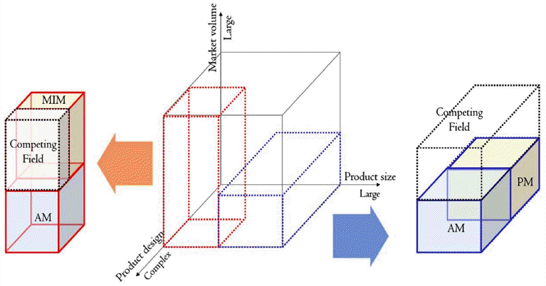
When you are looking at manufacturing system innovation, eliminated manufacturing concept should be intensively considered. Bottom-up manufacturing, computer aided manufacturing, and eliminated manufacturing concepts make AM technology competitive to powder metallurgy technology. Fig. 7 shows 3D competitiveness map between AM and PM according to product design, product size, and market volume. PM technology contains bottom-up manufacturing concept and it has also pursued net-shape production of complex products. However, it inherently needs tools. For low volume and large sized products, AM is superior to the conventional powder metallurgy technology because of design complexity by computer aided manufacturing, higher material utilization by bottom-up manufacturing, and tool-less manufacturing by eliminated manufacturing. Among them, toolless manufacturing of AM is advantageous over PM technology from the viewpoint of cost competitiveness. In the same fashion, AM can be potent main production methodology for low volume production of complex and small sized products. Metal injection molding has superiority in mass production of complex products. MiMed green body from injecting feedstock into mold is converted to brown body via debinding and final product is produced by sintering. Contrarily, metal AM eliminates mold in final product manufacturing. Additionally, product design, modification, and reengineering are cheap, fast, and facile. Multiple candidate products with different design are simultaneously manufactured without constraints from mold. As a matter of fact, MIM companies are missing business opportunities owing to risks arising at the product development stage. AM itself can be used to supply low volume market and mass personalization production which are inadequate for MIM. Otherwise, configurable manufacturing system between AM and MIM can be effective. Before MIM production, AM is used as intermediate method like RP or RM. AM is utilized for product design selection, MIM strategy development, and mold making for MIM.
Fig. 7

Market segmentation of AM from eliminated manufacturing concept.

KPMI-23-149_F7.gif
Direct assembly manufacturing rather than parts manufacturing is advantageous because time and cost consuming assembly processes are eliminated. CAD-to-SYSTEM approach that electronic components are in-situ embedded during AM is a good example which emphasize the important of eliminated manufacturing concept [90]. This makes AM much more flexible for personalized products manufacturing. Capital investment in particular for metal AM machines and post-processing systems affects cost structure of manufacturing system. In the centralized manufacturing era, manufacturing systems were optimized for dedicated production with simplified functions. However, flexible production system is recommended for volatile markets and mass personalization owing to enlarged product variants. AM is of potent possibilities for flexible production because of four fundamental concepts. Multiple products with different geometric shapes are simultaneously manufactured. AM can be used to product design optimization with easy re-engineering with minimum demands for tools. It markedly reduces lead time to market. From economics of scope, it is difficult to sustain cost-effectiveness in low volume manufacturing for a variety of products. Process savings improve capital investment costs, manufacturing costs and value chain management costs. However, it will need much time to be primary manufacturing system whether it is due to immaturity of current AM technology or chasms in disruptive innovation technology adoption. Current AM technology requires post-processing which needs to invest post-processing equipment or require value chains. Accordingly, genuine eliminated manufacturing concept is achieved when it eliminates post-processing in final product manufacturing.
Business model is differentiated according to created values, market characteristics, and non-market environments such as regulation, legislation, and governmental policies. It can be remarked that unprecedented values and governmental policies boost current AM technology to penetrate markets. Conclusively, conventional centralized production depends on big capital investment and labor-intensified manufacturing. It causes surplus of supply in global markets. Correspondingly, both low utilization efficiency of natural resources and substantial emissions which are coupled in carbon society increase retarded societal costs in the future. In addition, impacts of manufacturing industries on national economics is reconsidered and developed countries try to revive fundamentals of domestic manufacturing. New game changers are explored to shake current global economics on the basis of centralized production-global distribution. Four fundamental concepts make AM sharply contrasted to conventional SM and particularly, distributed manufacturing concept which is supported by the other concepts provides opportunities for developed countries to reconstruct their manufacturing industries. Traditionally, developed countries have strengths on knowledge intensified manufacturing, costing knowledge, intellectual properties management, advanced manufacturing system management, and global standardization. As a matter of fact, it is argued that AM is already competitive for job creation in specified market [91]. Accordingly, it is expected that AM as a personalized manufacturing enabler will push global market toward decentralized production and regional distribution.
Markets for AM are different from conventional markets so market should be firstly defined and segmented. Metal AM markets are generally in the introduction stage. Particular markets such as bio-devices including implants seems to enter growth phase because of market characteristics. Patient’s bio information such as geometric structure and mechanical strength of bone is generated with aids of tomography and FEM analysis [92]. Lots of researches on bio devices architectures, microstructures, and properties have been conducted. What are left are AM reliability, standardization, and permission. If all are satisfied by society, what kind of value chain will appear? Mass personalization may have duality. As manufacturing paradigm shift proceeds, product variants will be maximized and contrarily, standardization will selects materials and machines. If it is true, hospitals may have their own printing shops rather than collaborative division between hospitals and AM suppliers. In this case, competition is focused on achieving global standards for materials and machines. Ultimately, bait and hook model will be seen as was observed in 2D paper printer market (printer as bait for consumable and expensive cartridge). On the other hand, aerospace and automotive industries are fascinating markets for AM. Light weight components are particularly emphasized for fuel economics. However, it is harsh for AM to penetrate automotive industry. Though AM itself has advantages over competitive manufacturing technologies, what makes both markets different? Lifecycle cost analysis is helpful.
Lifecycle cost analysis covers cost structures from product conception to disposal. Conventionally, suppliers and customers are discrete and they form supply chains in industrial ecology. Producers consider product concept, product design, manufacturing design, production, and logistics while consumers take parts in purchase, using, maintenance, and disposal. In the decision making stage for adopting innovative products and manufacturing technology, customers consider various values which are suggested by new entrants. Energy savings by weight reduction of aircrafts are huge during operational use phase. Correspondingly, airline companies as well as aircraft manufacturers may be flexible for light-weight materials and components. Non-safety components are to be main market penetration targets of AM. SAVING project is a good example. It conducted replacement of steel or Al buckle with Ti buckle. When an airline company chooses Airbus A380 equipped with Ti buckles instead of steel buckles, weight reduction of 72.5 kg will be achieved and 3.3 million liters of fuel will be saved apart from CO2 emission reduction. When the airline company is hesitating between 2,000,000 pounds saving for use phase and 160,000 pounds expense for purchase phase, new entrant gives another values such as functional design to eliminate assembling step by direct building an integrated buckle. Finally, advantages of MRO (maintenance, repair, and overhaul) phase by AMon- demand are appealed.
Same approach will not work for automotive manufacturers. Light weighting strategy is indeed necessary for automakers and however, it should be remembered that cost is the primary factor for automotive components market. In the literature [93], impacts of weight reduction of 100 kg on energy consumption during use phase are estimated for various different vehicles/vessels. Regardless of vehicles/vessels, weight reduction results in energy reduction. Supposing that a private gasoline car runs 200,000 km and fuel saving rate is 0.5 l/(100 km- 100 kg), fuel saving of 1,000 liters is expected for whole life only when 100 kg weight reduction is achieved. As a result, weight reduction of several kg by expensive AM products have no influence on automakers though gross sum of fuel savings for global passenger cars is huge. Automotive industry has different sensitivity to light weight and fuel economics from aircraft industry. Nevertheless, RP and RM are extensively used in automotive industry. Freedom of design and redesign, fast response time, and reduction of product development cost are accomplished by four fundamental concepts. Otherwise, luxury cars or after sales markets may be market penetration points for AM because customer with higher purchasing power may cost personalized quality. In this case, accessibility of customers to manufacturers and product selectivity need to be enhanced.
Koren suggests open structured products which is defined as “a product designed so that components (i.e. modules) can be added to its original structure or swapped in order to change product features” [94]. It implies that engagements of customers for products will be enhanced: customers will define their own products, purchase modules, and assembly them. To do this, original open architecture product acts as a platform and multiple functional modules are easily adaptive to it. Jimmy, an android robot, of Intel and Trossen Robotics is a good indicator for near future open architecture product markets coupled with additive manufacturing. One can finalize one’s own robot using AM with unprintable hardware modules such as batteries, object identification modules, electromechanical modules, IoT modules. Open architecture products will be flourishing on the basis of open resources. AM products will start with simple passive components. However, it will expand to more complicated active modules as electronic components embedded products manufacturing technology is maturing. At that time, open architectural products manufactures work together with module developers and suppliers as smartphone-makers work with app. developers. Long-tail AM markets are enabled with interactive internet environment and delivery network. In these contexts, on-line 2D printing business coupled with delivery business can be precedent for future AM markets. A customer uploads and pays his/her printable files through website or app. of a printing shop. Printed stuff is delivered to door. Ubiquitous AM chains will appear by capital investments to AM shops, AM machines, and infrastructures. Standard materials and machines are again emphasized from the viewpoint of supply side.
There have been lots of innovative technologies in history of manufacturing. Part of them were adopted in industries, part of them disappeared, and part of them were renovated and accepted later. As previously discussed, AM has potent possibility to change manufacturing hierarchy. However, it also suffers from chasms in a similar manner of previous innovation technologies. Three biases are commonly observed when AM technology is transferred to industries.
5.1 Visionary bias
Moore pointed out a big chasm in innovation technology adoption cycle, especially between early adopters and early massive adopter from the viewpoint of psychographics. Early adopters show enthusiasm for AM technology and however, early majority analyze AM technology from practical viewpoints. AM technology is regarded as disruptive innovation but early majority prefers continuous innovation. Early majority has better understanding on market characteristics while early adopter understands technology very well. Moreover, there are not sufficient references of failures in adoption of AM.
5.2 Selection bias
A child who is standing in a toy store with one choice of his/her birthday present may suffer from stressful selection bias. Similarly, there are too many AM processes and they have their own advantages and disadvantages. Selection of AM process is difficult and risky for companies. In decision making, payback period for investment is crucial especially for small and medium sized companies.
5.3 Onion-peeling bias
Once you buy an AM machine, can you generate what you think as 3D model? It needs much time to be expertized. When you have your own 3D model, what process parameters and manufacturing strategy do you conduct? How about post-AM processes? How do you guarantee your products to your customer? Furthermore, when a customer ask you to supply some products from new materials, what do you do? Model generation, optimum process strategy, evaluation, material selectivity, and post AM processes require high level knowledge. It is known that Arcam that sells electron beam powder bed fusion AM equipment took about 2 years before it achieve standardization for Ti-6Al-4V EL [95]. That is to say, hurdles are continuously appearing in an additive manner before AM companies become proficient.
In order to cross the chasms, AM technology is now renovated from practical standpoints. R&D activities for user friendly pre-AM technology from 3D model generation to product packing algorithm are conducted. With respects to AM, in-situ monitoring and feedback system is equipped to AM machine for product quality and process reliability. Productivity is enhanced by increasing power of individual energy sources or adoption of multiple energy sources. Equipment cost will be lowered by competition between participants in growing market. It is challenging to wide materials selectivity with significantly reduced prices. Post processes which are compatible and cost-effective needs to be diversified.
When current state of AM technology is considered, it is not full automation technology yet. Therefore, collaboration with conventional technology is extensively studied. In Republic of Korea, dual tracks of metal AM development strategy are considered on the basis of time dependent AM technology revolution. Ultimately, AM technology will compete with traditional manufacturing technologies. However, collaboration with fundamental manufacturing is effective before being push button technology. AM can assist fundamental manufacturing technologies as previously mentioned. To the contrary, fundamental manufacturing technologies complement current AM technology. If laser powder bed fusion AM is taken for example, powder flowability and packing have been extensively studied in powder technology [96- 98]. Phenomena involved in weld pool formations are dealt in laser welding metallurgy [99-102]. Traditional materials treatment processes are applied for post-AM processing. Additionally, it is noted that hybrid AM processes, active collaboration between AM and SM, are emerging recently. In-situ coupling between directed energy deposition AM and machining [103], alternate manufacturing of powder bed fusion AM and machining [104], binder jetting and direct sintering [105], and hybrid RP system of FDM and machining [106] are suggested. On the other hand, binder jetting metal AM makes primitives and then debinding and sintering are subsequent as MIM does. As a result, introduction of binder jetting AM to MIM companies is effective rather than melting base metal AMs because they utilize debinding and sintering processes and equipment which they are accustomed. This is another strategy to cross chasm by minimizing discontinuities of AM adoption. Standardization is an effective methodology to provide AM ecology with dependability. Standards cover performance measurement of devices, specification of performance requirements for devices, specification of general performance for a range of devices, requirements for quality assurance, codes of practices, technical reports, definition of glossaries, and so on. However, it is also noted that standardization has duality. Increase of reliability on whole scope of process and reduction of risk are positive benefits from standardization. To the contrary, leading groups will take benefits from standards and the standardization makes it difficult for later entrants to penetrate market. Standards for medical devices limit AM materials and AM processes and therefore, efforts to advance AM technology will be shrunk by conservative markets.
Manufacturing technology has been persistently evolved for satisfying market demands and simultaneously it has contributed to societal changes. Koren argues that manufacturing paradigm has been shifted from craft production to personalized manufacturing via mass production and mass customization in globalized economics. Indeed, paradigm transition was supported by advances in products, manufacturing systems, and business models. It is also emphasized that open-architecture products will be prevailing by diversified manufacturing systems which support responsive business model. With respect to manufacturing system, reconfigurable manufacturing system is suggested to satisfy the personalized and/or regional productions in addition to conventional dedicated system and flexible system. In these contexts, additive manufacturing technology can be a potent driving force to transition manufacturing paradigm toward so called mass personalization if it can cross the current chasms successfully. Four fundamental concepts which were considered in the present study allow us to develop open architecture products, flexible and responsive manufacturing systems to volatile markets, diversified business opportunities, decentralized manufacturing, and manufacturing-on-demands. Utilization efficiency of resources and reduction of whole life-cycle emissions can be further achieved via exploitation of four fundamental concepts of additive manufacturing. From the marketing aspects, AM technology in particular for metal AM is in the introduction stage. Materials selectivity, facile models generation, in-situ diagnostics and feedback machine system, effective post- AM processes, and standard dependability are further developed to cross current chasms related to emerging innovative AM technology to say nothing of cost-effectiveness and productivity. Complementary integrations between AM and fundamental manufacturing processes before full automated AM technology can be potent options for stepping steps before push-button AM technology. Powder metallurgy is a matured fundamental manufacturing technology. Swarm intelligence of powder metallurgy society is really helpful to improve additive manufacturing technology and vice versa, powder metallurgy companies will have more business opportunities by adopting AM technology.
Acknowledgements
The study was conducted by the Korea Institute of Industrial Technology and Hanyang University.
  • 1. J Moavenzadeh, The Future of Manufacturing: Opportunities to drive economic growth, A world Economic Forum Report. (2012) Puerto Vallarta
  • 2. ASTM F2792-12aStandard Terminology for Additive Manufacturing Technologies.
  • 3. F M Amirouche, Principles of Computer-Aided Design and Manufacturing, (2004) Pearson/Prentice Hall, Chicago
  • 4. G Farin and J Hoschek, Handbook of Computer Aided Geometric Design, (2002) Elsevier, Amsterdam
  • 5. Y E Kalay, Architecture’s New Media: Principles, Theories, and Methods of Computer-Aided Design. (2004) The MIT Press, London
  • 6. J Wang and D Gu: Comput. Ind. Eng., (2012) 63 1189.Article
  • 7. C Beccari and E Farella: Comput. Aided Design., (2010) 42 860.Article
  • 8. R B Fisher: Comput. Aided Design., (2004) 36 501.Article
  • 9. H Aoki, J Mitani, Y Kanamori and Y J Fukui: Comput. Des. Eng., (2015) 2 47.ArticlePDF
  • 10. H Brodin and J Saarimaki, Mechanical properties of lattice truss structures made of a selective laser melted superalloy, ScholarlyEditions(2013) Beijing
  • 11. E Lin and M C Boyce: J. Mech. Phys. Solids., (2014) 73 166.Article
  • 12. R Paul and S Anand: Comput. Aided Design., (2015) 63 86.Article
  • 13. I Braude, M.S. Thesis, Smooth 3D Surface Reconstruction from Contours of Biological Data with MPU Implicits. (2005) Drexel University, Philadelphia
  • 14. B Cheng and K Chou: Comput. Aided Design., (2015) 69 102.Article
  • 15. K Hu, S Jin and C C L Wang: Comput. Aided Design., (2015) 65 1.Article
  • 16. K A Dowsland and W B Dowsland: Eur. J. Oper. Res., (1992) 56 2.Article
  • 17. J M V de Carvalho: Eur. J. Oper. Res., (2002) 141 253.
  • 18. Y Zhang and A Bernard: Procedia CIRP., (2014) 17 308.Article
  • 19. D dimitrov, N de Beer, P Hugo and K Schreve: Compr. Mater. Process., (2014) 10 217.
  • 20. S Maleksaeedi, H Eng, F E Wiria, T M H Ha and Z He: J. Mater. Process. Tech., (2014) 214 1301.Article
  • 21. B Utela, D Storti, R Anderson and M Ganter: J. Manuf. Processes., (2013) 10 96.Article
  • 22. M Truker, D Godlinski and F Petzoldt: Mater. Charact., (2008) 59 1728.
  • 23. T T Lamminmaki, J P Kettle, P J T Puukko, C J Ridgway and P A C Gane: J. Colloid Interface Sci., (2012) 365 222.
  • 24. L Song and J Mazumder: IEEE Sens. J., (2012) 12 958.Article
  • 25. L Song, V Bagavath-Singh, B Dutta and J Mazumder: Int. J. Adv. Manuf. Technol., (2011) 58 247.ArticlePDF
  • 26. K Bartkowiak: Phys. Procedia., (2010) 5 623.Article
  • 27. J C Heigel, P Michaleris and E W Reutzel: Addit. Manuf., (2015) 5 9.Article
  • 28. A Raghavan, H L Wei, T A Palmer and T Debroy: J. Laser Appl., (2013) 25 052006.
  • 29. B N Turner, R Strong and S A Gold: Rapid Prototyping J., (2014) 20 192.
  • 30. B N Turner, R Strong and S A Gold: Rapid Prototyping J., (2015) 21 250.Article
  • 31. Y Jin, Y He, J Fu, W Gan and Z Lin: Addit. Manuf., (2015) 1-4 32.Article
  • 32. C B Williams, F Mistree and D W Rosen, Towards The Design of A Layer-Based Additive Manufacturing Process for The Realization of Metal Parts of Designed Mesostructure. SFF Symp. (2005) . p. 217.
  • 33. B N Turner, R Strong and S A Gold: Rapid Prototyping J., (2014) 20 192.
  • 34. D Blanco, P Fernandez and A Noriega: J. Mater. Res., (2014) 29 1876.Article
  • 35. S Meteyer, X Xu, N Perry and Y F Zhao: Procedia CIRP., (2014) 15 19.Article
  • 36. X Xu, S Meteyer, N Perry and Y F Zhao: Int. J. Prod. Res., (2015) 53 7005.Article
  • 37. A T Gaynor, N A Meisel, C B Williams and J K Guest: J. Manuf. Sci. E-T. ASME., (2014) 136 061015–1,
  • 38. T Caffrey and T Wohlers: Manuf. Eng., (2015) 154 67.
  • 39. B Reinarz, J T Sehrt, G Witt, J V Kampen, J Munzer and M Ott, Optimization of media feed channels in Laser Beam Melting. Proc. ASPE. (2014) Berkeley. p. 13.
  • 40. M Jamshidinia, A Sadek, W Wang and S Kelly: Addit. Manuf., (2015) 173 20.ArticlePDF
  • 41. W S Land, B Zhang, J Ziegert and A Davies: Procedia Manuf., (2015) 1 393.Article
  • 42. P F Zheng, L C Chan and T C Lee: Finite Elem. Anal. Des., (2005) 42 189.Article
  • 43. R Holker, A Jager, N B Khalifa and A E Tekkaya: Int. J. Precis. Eng. Manuf., (2013) 14 1487.ArticlePDF
  • 44. A Atrian and F Fereshteh-Saniee: Compos. Part. BENG., (2013) 47 75.Article
  • 45. M H Parsa and K Yamaguchi: Int. J. Mech. Sci., (2001) 43 2331.Article
  • 46. M G Serror and J Inoue: J. Mech. Eng., (2013) 139 94.Article
  • 47. A Torregaray and C Garcia: Mater. Design., (2009) 30 4570.Article
  • 48. X Xiao, C Hsiung and Z Zhao: Int. J. Mech. Sci., (2008) 50 69.Article
  • 49. I Gibson, D Rosen and B Stucker, Additive Manufacturing Technologies, (2015) Springer, New York 63.
  • 50. K Itoga, M Yamato, J Kobayashi, A Kikuchi and T Okano: Biomaterials., (2004) 25 2047.Article
  • 51. L H Nguyen, M Straub and M Gu: Adv. Funct. Mater., (2005) 15 209.Article
  • 52. S Moylan, J Slotwinski, A Cooke, K Jurrens and M A Donmez: J. Res. Natl. Inst. Stan., (2014) 119 429.Article
  • 53. Y Lu and S Chen: Appl. Phys. Lett., (2008) 92 041109.
  • 54. K Shahzad, J Deckers, JP Druth and J Vleugels: J. Mater. Process. Tech., (2013) 213 1484.Article
  • 55. S M Gaytan, M A Cadena, H Karim, D Delfin, Y Lin, D Espalin, E MacDonald and R B Wicker: Ceram. Int., (2015) 41 6610.Article
  • 56. S M Giannitelli, P Mozetic, M Trombetta and A Rainer: Acta Biomater., (2015) 24 1.Article
  • 57. J Wan, J M Gasch and K A Mukherjee: J. Mater. Res., (2001) 16 3274.Article
  • 58. G Pyka, A Burakowski, G Kerckhofs, M Moesen, S V Bael, J Schrooten and M Wevers: Adv. Eng. Mater., (2012) 14 363.Article
  • 59. E Uhlmann, C Schmiedel and J Wendler: Procedia CIRP., (2015) 31 209.Article
  • 60. T B Kim, S Yue, Z Zhang, E Jones, J R Jones and P D Lee: J. Mater. Process. Tech., (2014) 214 2706.Article
  • 61. Y H Liu, D Hirama and S Matsusaka: Powder Technol., (2012) 217 607.Article
  • 62. M P Matheny and K F Graff, Powder Ultrasonics: Applications of High-Intensity Ultrasound(2014) Woodhead, London
  • 63. S Das, M Wohlert, J J Beaman and D L Bourell: Mater. Design., (1999) 20 115.Article
  • 64. E O Olakanmi, R F Cochrane and K W Dalgarno: Prog. Mater. Sci., (2015) 74 401.Article
  • 65. T Wohlers, Wohlers Report 2014: 3D printing and Additive Manufacturing State of the Industry. (2014) Colorado
  • 66. J E Barnes, J Williams, C A Blue and B Peter: Titanium powder metallurgy-What's after the kroll process? Int. Titan. Assoc., (2012)
  • 67. R M German: PIM Int., (2009) 3 21.
  • 68. R M German, Particle Packing Characteristics, (1989) Metal Powder Industries Federation, Princeton
  • 69. A J Pinkerton and L Li: Int. J. Adv. Manuf. Technol., (2005) 25 471.ArticlePDF
  • 70. A J Pinkerton and L Li: J. Eng. Manuf., (2003) 217 741.ArticlePDF
  • 71. S Kumar and J P Kruth: (2007) 28 400.
  • 72. A Simchi and H Pohl: Mater. Sci. Eng. A., (2004) 383 191.Article
  • 73. K Maeda and T H C Chids: J. Mater. Process. Tech., (2004) 149 609.Article
  • 74. A Gaard, P Krakhmalev and J Bergstrom: J. Alloy. Compd., (2006) 421 166.
  • 75. E Yu and G B Shaffer: Acta Mat., (2009) 57 163.Article
  • 76. L Lu, J Y H Fuh, Z D Chen, C C Leong and Y S Wong: Mater. Res. Bull., (2000) 35 1555.Article
  • 77. X C Li, J Stampfl and F B Prinz: Mater. Sci. Eng. A., (2000) 282 86.Article
  • 78. S H Masood and W Q Song: Mater. Design., (2004) 25 587.Article
  • 79. C Hong, D Gu, D Dai, M Alkjayat, W Urban, P Yuan, S Cao, A Gasser, A Weisheit, I Kelbassa, M Zhong and R Poprawe: Mater. Sci. Eng. A., (2015) 635 118.Article
  • 80. D E Cooper, N Blundell, S Maggs and G J Gibbons: J. Mater. Process. Tech., (2013) 213 2191.Article
  • 81. D Gu, H Wang, F Chang, D Dai, P Yuan, Y Hagedorn and W Meiners: Physics Procedia., (2014) 56 108.Article
  • 82. A Emamian, M Alimardani and A J Khajepour: Manuf. Processes., (2014) 16 511.Article
  • 83. M Vaezi, H Seitz and S Yang: Int. J. Adv. Manuf. Tech., (2013) 67 1721.ArticlePDF
  • 84. S Lim, R A Buswell, T T Le, S A Austin, A G F Gibb and T Thorpe: Automat. Constr., (2012) 21 262.Article
  • 85. T Brajlih, B Valentan, J Balic and D Igor: ‘Speed and accuracy evaluation of additive manufacturing machines’. Rapid Prototyping J., (2011) 17 64.Article
  • 86. D Salehi and M Brandt: Int. J. Adv. Manuf. Technol., (2006) 29 273.ArticlePDF
  • 87. H Gharavi and R Ghafurian, Smart Grid: The Electric energy system of the future. P. IEEE. (2011) Shanghai. 99 p. 917.Article
  • 88. J R Nicholls, N J Simms, W Y Chan and H E Evans: Surf. Coat. Tech., (2002) 149 236.Article
  • 89. D Dudzinski, A Devillez, A Moufki, D Larrouquere, V Zerrouki and J Vigneau: Int. J. Mach. Tool. Manu., (2004) 44 439.Article
  • 90. C Holshouser, C Newell, S Palas, C duty, L Love, V Kunc, R Lind, P Lloyd, R Degoff, W Peter and C Blue: Adv. Mater. Process., (2013) 171 15.ArticlePDF
  • 91. B Kianian, S Tavassoli and T C Larsson: Procedia CIRP., (2015) 26 93.Article
  • 92. R Haux: Int. J. Med. Inform., (2006) 75 268.Article
  • 93. A D Brooker, J Ward and L Wang: SAE Int. J., (2013) 2.
  • 94. Y Koren, S J Hu, P Gu and M Shpitalni: CIRP Ann- Manuf. Technol., (2013) 62 719.Article
  • 95. P A Kobryn and S Semiatin: L JOM-US., (2001) 53 40.ArticlePDF
  • 96. Y Y Sun, S Gulizia, C H Oh, C Doblin, Y F Yang and M Qiani: JOM-US., (2015) 67 564.ArticlePDF
  • 97. B Baufeld, O V D Biest and R Gault: Mater. Design., (2010) 31 106.
  • 98. J A Slotwinski, E J Garboczi, P E Stutzman, C F Ferraris, S S Watson and M A Peltz: J. Res. Natl. Inst. Stan., (2014) 119 460.Article
  • 99. M Akira, S Naoki, J-D Kim, M Masami and K Seiji: Proc. SPIE: Int. Soc. Opt. Eng., (2000) 3888 34.
  • 100. G Li, Y Cai and Y Wu: Opt. Laser. Eng., (2009) 47 990.Article
  • 101. K Y Benyounis, A G Olabi and M S J Hashmi: J. Mater. Process. Tech., (2005) 164-165 978.Article
  • 102. B S Yilbas, A F M Arif and B J A Aleem: Opt. Laser. Tech., (2010) 42 760.Article
  • 103. J C Heigel, P Michaleris and E W Reutzel: Addit. Manuf., (2015) 5 9.Article
  • 104. W E King, H D Barth, V M Castillo, G F Gallegos, J W Gibbs, D E Hahn, C Kamath and A M Rubenchik: J. Mater. Process. Tech., (2014) 214 2915.Article
  • 105. S M Gaytan, M A Cadena, H Karim, D Delfin, Y Lin, D Espalin, E MacDonald and R B Wicker: Ceram. Int., (2015) 41 6610.Article
  • 106. W C Lee, C C Wei and S C Chung: J. Mater. Process. Tech., (2014) 214 2366.Article

Figure & Data

References

    Citations

    Citations to this article as recorded by  
    • SiC-Si composite part fabrication via SiC powder binder jetting additive manufacturing and molten-Si infiltration
      Ji-Won Oh, Jinsu Park, Sahn Nahm, Hanshin Choi
      International Journal of Refractory Metals and Hard Materials.2021; 101: 105686.     CrossRef
    • Recent Trends and Application Status of the Metal Matrix Composites (MMCs)
      Hyo-Seop Kim
      Journal of Korean Powder Metallurgy Institute.2020; 27(2): 164.     CrossRef
    • Metal Additive Manufacturing Cycle in Aerospace Industry: A Comprehensive Review
      B. Barroqueiro, A. Andrade-Campos, R. A. F. Valente, V. Neto
      Journal of Manufacturing and Materials Processing.2019; 3(3): 52.     CrossRef
    • Technology Trend of the additive Manufacturing (AM)
      Ji-Won Oh, Hyunwoong Na, Hanshin Choi
      Journal of Korean Powder Metallurgy Institute.2017; 24(6): 494.     CrossRef

    • PubReader PubReader
    • Cite this Article
      Cite this Article
      export Copy Download
      Close
      Download Citation
      Download a citation file in RIS format that can be imported by all major citation management software, including EndNote, ProCite, RefWorks, and Reference Manager.

      Format:
      • RIS — For EndNote, ProCite, RefWorks, and most other reference management software
      • BibTeX — For JabRef, BibDesk, and other BibTeX-specific software
      Include:
      • Citation for the content below
      Research Trend of Additive Manufacturing Technology
      J Korean Powder Metall Inst. 2016;23(2):149-169.   Published online April 1, 2016
      Close
    • XML DownloadXML Download
    Figure
    • 0
    • 1
    • 2
    • 3
    • 4
    • 5
    • 6
    Related articles
    Research Trend of Additive Manufacturing Technology
    Image Image Image Image Image Image Image
    Fig. 1 Example of post-processing of directed energy deposition AM product.
    Fig. 2 Metal additive manufacturing process according to feedstock dimension and process temperature.
    Fig. 3 Metal markets and market share of metal additive manufacturing; (a) Metal markets (b) Market share of metal AM.
    Fig. 4 Ti and Ti alloy prices according to powder preparation method (price range results from chemical composition).
    Fig. 5 Ti and Ti alloy prices according to powder preparation method (price range results from chemical composition).
    Fig. 6 Micro-components AM technology, general AM technology, and construction scaled AM.
    Fig. 7 Market segmentation of AM from eliminated manufacturing concept.
    Research Trend of Additive Manufacturing Technology
    Standardgroup Characteristics Materials

    Materials Consolidation mechanism Polymer Metal Ceramic Composite

    Binder jetting Powders Binders Polymerization O O O O
    Directed energy deposition Powders Wires Melting-solidification O O O O
    Material extrusion Wires Extrusion-polymerization O O O O
    Material jetting Photopolymer Wax Photopolymerization O O O
    Powder bed fusion Powders Melting-solidification O O O O
    Solid/liquid phase sintering
    Sheet lamination Sheets Wires Bonding Joining/welding O O O
    Vat Photo-polymerization Photo-polymers Photopolymerization O O O
    Divisionc Polymers Metals Ceramics Composites

    AM materials Thermoplastics
    Thermosets
    Photopolymers
    Elastomers
    Powders
    Wires
    Sheets
    Structural ceramics
    Functional ceramics
    Bio-ceramics
    PMC
    MMC
    CMC
    ASTM classification Commercialized process (Maker) Process time* Properties

    Relative density (%) Accuracy (mm) Surface roughness (Ra/um)

    Binder jetting Digital part materialization (ExOne) 10 hours** > 95*** ~ +/- 2.0 ~ 9
    Powder bed fusion Electron beam melting (Arcam AB) 12 hours > 99 ~ +/- 0.2 ~ 20
    Directed metal laser sintering (EOS) Laser engineered net shaping (Optomec) 24 hours > 99 ~ +/- 0.05 ~ 9
    Directed energy deposition Ultrasonic additive manufacturing 10 hours > 99 ~ +/- 0.125 ~ 25
    Sheet lamination (Fabrisonic LLC) 24 hours > 99 ~+/- 0.015 ~ 7
    Applications Metal powders Powder suppliers

    Medical devices
    Aerospace components
    Molds
    Automotives
    Energy
    Custom/jewelry
    Others
    Pure Ti/Ti-6Al-4V
    Co alloys
    (CoCr, CoCrMo)
    Al alloys
    (AlSi, AlSiMg, AlMgSc, 7XXX)
    Ni alloys
    (IN 625, IN 718)
    Fe alloys
    (316L STS, Maraging, 17-4 PH)
    LPW Technology Ltd
    Sandvik Materials Technology
    H ganas AB
    Carpenter Technology Corp.
    Allegheny Technologies Incorporated
    H.S. Starck
    Additive Metal Alloys
    Advanced Powders & coatings
    CSIRO
    Nanosteel
    Cooksongold
    Powder production process Morphology Size (median/um) Impurities Reference

    O C

    Kroll (sponge fine) Irregular/facet 180-800 0.35 0.05 66
    Hunter (sponge fine) Irregular/facet 180-800 0.35 0.05 67
    FFC Cambridge (crushed powder) Irregular/facet 0.40 68
    HDH powder Irregular/facet 38 0.25 0.04 66
    Gas atomization Spherical 32 0.15 0.03 69
    Plasma rotating electrode process Spherical 130 0.15 0.02 70
    Plasma atomization Spherical 60 0.15 0.04 71
    Powder Process Shape D50, μm Distribution Flow time, S Cost

    Al gas atomized spherical 30 moderate nf moderate
    Co alloy gas atomized spherical 90 -
    Fe gas atomized spherical 66 9
    stainless gas atomized spherical 12 3.8
    TiAl gas atomized spherical 180 30

    Cu water atomized nodular 62 wide 48 low
    Fe water atomized irregular 75 26
    Pb water atomized ligamental 42 24
    stainless water atomized irregular 60 2.6
    tool steel water atomized nodular 70 50

    Fe Centrifugal spherical 75 moderate 14 high
    Ti alloy Centrifugal spherical 175 28
    Division Unit Selective laser melting Electron beam melting Laser metal deposition Selective laser sintering

    Equipment SLM 280HL (SLM Solutions) Arcam A2 (Arcam) Trumpf HLD 3504 (Trumpf) EOSINT M270 (EOS)
    Build volume mm3 280×280×350 250×250×400 250×250×215
    Beam size, in general um ~120 ~500 ~4100 ~500
    Scanning speed in general mm/s ~800 ~800 ~40 ~100
    Atmosphere Inert gas Vacuum Ar shielding gas Inert environment
    Layer thickness um ~75 ~100 ~400 ~100
    Feedstock um Powder (~50) Powder (~150) Powder (~200) Powder (~74)
    ASTM group Powder bed fusion Directed energy deposition Powder bed fusion
    Powder Powder preparation AM process Ref.

    Fe-C (graphite) Tumbling mixing (0, 0.4, 0.8, 1.2, 1.6 wt.% C) Selective laser sintering 72
    WC-Co Granulation (4, 10 wt.% Co) Selective laser sintering Bronze infiltration 73
    Invar 36 (Fe-Ni)-TiC Blended powder (30, 60, 80 wt.% TiC) Direct metal laser sintering 74
    AA6061-Mg-Sn-Nylon Blended powder (2 wt.% Mg, 1 wt.% Sn, 3 wt.% nylon) Selective laser sintering AA6061 infiltration 75
    Cu-Ti-C-Ni Mixture (planetary ball milling) Selective laser sintering In-situ carburization 76
    Invar 36-TiC Powder mixture (0, 6.6, 14.3, 22.1, 29.4, 52.1 vol.% TiC) Direct laser deposition 77
    Fe-Nylon Filament (30, 40 vol.% Fe) Fused deposition modeling 78
    IN 625-TiC Planetary ball mixing (5 wt.% TiC) Laser metal deposition 79
    IN 625-Al2O3
    IN 625-SiC
    IM 625-TiC
    Ball mixing (5 wt.% additives) Laser powder bed fusion 80
    AlSi10Mg-TiC Ball mixing (5 wt.% TiC nanoparticle) Selective laser melting 81
    Fe-Ti-C Ball mixing (24.9 wt.% Ti, 5.1 wt.% C) Laser additive manufacturing (directed energy deposition) 82
    Table 1. Characteristics and commercial processes of each AM group in ASTM standard

    Table 2. Additive manufacturing materials

    Table 3. Comparison of metal additive manufacturing processes [65]

    Process time: time generally required for making 125×125×125 mm3 cube product

    Time for primitive product by binder jetting AM excluding post-processing (debinding and sintering)

    Relative density after sintering

    Table 4. Metal powders and suppliers

    Table 5. Comparison of Ti powders from different production processes

    Table 6. Example Powders and Characteristics by Various Processes [72]

    nf: Non-flow

    Table 7. Features of commercialized processes in Metal powder AM processes

    Table 8. Example studies of metal matrix compoite AM


    Journal of Powder Materials : Journal of Powder Materials
    TOP