Articles
- Page Path
- HOME > J Korean Powder Metall Inst > Volume 24(1); 2017 > Article
-
Article
- Representative Volume Element Analysis of Fluid-Structure Interaction Effect on Graphite Powder Based Active Material for Lithium-Ion Batteries
- Jin Chul Yun, Seong Jin Park*
-
Journal of Korean Powder Metallurgy Institute 2017;24(1):17-23.
DOI: https://doi.org/10.4150/KPMI.2017.24.1.17
Published online: January 31, 2017
Department of Mechanical Engineering, Pohang University of Science and Technology, 77 Cheongam-Ro, Nam-Gu, Pohang, Gyeongbuk 37673, Republic of Korea
- * Corresponding Author: Seong Jin Park, TEL: +82-54-279-2182, FAX: +82-54-279-5899, E-mail: sjpark87@postech.ac.kr
© The Korean Powder Metallurgy Institute. All rights reserved.
- 669 Views
- 3 Download
Abstract
- In this study, a finite element analysis approach is proposed to predict the fluid-structure interaction behavior of active materials for lithium-ion batteries (LIBs), which are mainly composed of graphite powder. The porous matrix of graphite powder saturated with fluid electrolyte is considered a representative volume element (RVE) model. Three different RVE models are proposed to consider the uncertainty of the powder shape and the porosity. Pwave modulus from RVE solutions are analyzed based on the microstructure and the interaction between the fluid and the graphite powder matrix. From the results, it is found that the large surface area of the active material results in low mechanical properties of LIB, which leads to poor structural durability when subjected to dynamic loads. The results obtained in this study provide useful information for predicting the mechanical safety of a battery pack.
- To address the depletion of fossil fuels and environmental pollution, there has been growing interest in electric vehicles (EVs) as alternatives to gasoline and diesel vehicles. Moreover, demand for hybrid electric vehicles (HEVs) with maximal fuel efficiency is gradually increasing. For EVs and HEVs, a rechargeable secondary battery is generally used as the electrical energy source. There are various types of secondary battery, such as lithium-ion, nickel-cadmium, and nickel-metal hydride devices. Among them, the lithium-ion battery (LIB) is used most widely because it has no memory effect, a high energy density, and a high voltage [1]. LIBs are currently used as the power sources for various mobile devices because their feasibility has been demonstrated. When using LIBs in automobiles, however, all possibilities in accidents than could occur should be considered to guarantee the safety of passengers. In particular, the weight of LIBs required to drive a single EV is in the hundreds of kilograms. Thus, it is important to understand mechanical behaviors of LIBs for the optimum design of EVs [2].
- LIBs are mainly composed of the anode & cathode electrode, which are coated with the porous active materials, soaked in the fluid electrolyte. Porous active materials for the anode and the cathode electrode are mainly composed of the graphite powder and the lithium oxide metal, respectively. Since the active materials are porous, fluids are filled in the pore of the matrix. Thus, interaction between the solid matrix and the fluid should be examined to predict mechanical behaviour of LIBs accurately. Porous media saturated with fluid has been studied in various fields such as soil mechanics, biomechanics, hydromechanics, etc [3-5]. But there are little studies about the mechanical behaviour of LIBs active materials, composed of the porous matrix saturated with electrolyte.
- In this study, a fluid-structure interaction (FSI) modelling approach is proposed to predict the mechanical behavior of the anode active materials for lithium-ion battery (LIB). Porous matrix saturated with fluid electrolyte is considered as a representative volume element (RVE) model. 3 different RVE models are proposed to consider the uncertainty of the actual microstructure of the active materials. P-wave modulus of RVE model is estimated from harmonic analyses. From defined models, parametric studies were conducted to analyze the effect of the microstructure and the interaction between the fluid electrolyte and the graphite powder matrix.
1. Introduction
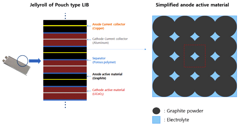
- Active materials of the anode electrolyte for LIBs are focused in this study. Graphite powder with size of 30~80 μm are generally applied for anode electrode [6]. Graphite powders are attached to each other by polymeric PVDF binder [7]. The compacted graphite powder forms porous matrix, which is fully saturated with fluid electrolyte (Fig. 1).
2. Microstructures of Active Materials
- 3.1. Definition of RVE models
- To apply RVE analysis for the active materials, some assumptions were applied as below:
1) Graphite powders are basically spherical with same diameter (65 μm), which can be overlapped as the compaction ratio increases.
2) Graphite powders and the polymeric binders are simplified to have equivalent stiffness and considered as one body.
3) Porous matrix has simplified periodic structures such as simple cubic (SC), body centered cubic (BCC) and face centered cubic (FCC) system.
- The RVE must be sufficiently large to contain all of the microscale properties of the components so as to represent equivalent material properties exactly. However, the accuracy of the RVE increases as its size decreases because of the boundary effect in macroscopic conditions [8]. Thus, the minimum size of RVE that contains every component and microstructure was determined in this study (Fig. 2).
- 3.2. Microstructure of the graphite powder matrix
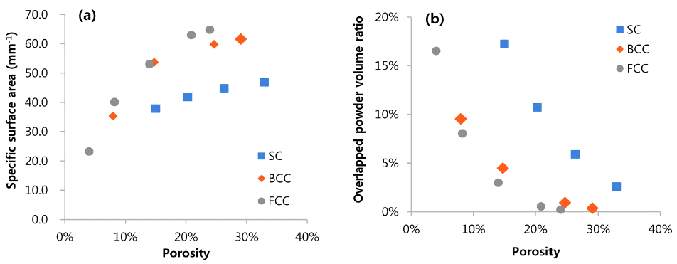
- LIBs of the pouch type cell is generally assembled to the module under the uniform pressure. As the assembly pressure increases, porosity of the active material decreases by the change of the microstructure of the graphite powder based matrix. Porosity is defined by the ratio of the volume of the fluid to the volume of the RVE. To identify the effect of the assembly pressure condition to the FSI behavior of the active material, parametric studies were conducted on the porosity of the powder matrix. Porosity was controlled by the volume of the overlapped graphite powders in the different types of RVEs. As the microstructure of the RVE changes, geometrical characteristics showed different characteristics (Fig. 3). As the porosity increases, “specific surface area” (ratio of the interface surface area to the RVE volume) increases for all types of RVEs. But “overlapped powder volume coefficient” (ratio of the overlapped powder volume to the RVE volume) is decreased as the porosity increased.
- 3.3. Governing equation
- To predict fluid-structure interaction of the active materials, acoustic harmonic analysis were conducted by using ANSYS Multiphysics. Governing equation of the solid matrix follows the well-known equation of motion:
- Where [Ms], [Cs] and [Ks] are the mass, damping, and stiffness matrices, respectively, and {fs} and {ue} is the external force and the displacement vector in the solid matrix, respectively. Acoustic wave equation for the fluid electrolyte in the porous matrix follows the modified equation of Stoke’s flow:
- where [MF], [CF] and [KF] are the mass, damping, and stiffness matrices, respectively, and {fF} and {pe} is the external force and the pressure vector in the acoustic fluid, respectively. Interaction between the solid matrix and the fluid assumes: a) there is no friction between the solid and acoustic fluid on the interface b) the solid stress equals to the fluid pressure imposed on the interface. To solve the harmonic behavior of the RVEs with both solid and fluid, a fully coupled finite element dynamic matrix equation is formulated:
- where [R] is the coupled matrix and represents the coupling conditions on the interface between the acoustic fluid and the solid matrix. All mechanical properties applied to the analysis are listed in Table 1.
- 3.4. Boundary condition
- This study is mainly focused on the vibration characteristics of the active materials. Thus, P-wave modulus was selected to measure the mechanical properties of the RVEs. For this purpose, boundary conditions are applied as follows:
- Where L is the length of the RVE, ui and P is the displacement and the pressure boundary conditions, respectively. Fluid pressure in the porous media (PF) is estimated by followed equation:
- Where Pext is the pressure applied to the solid matrix and α is the normalized fluid pressure (0 ≤ α ≤ 1). In this study, the effect of the fluid pressure was analyzed by applying various α (from 0 to 1).
- From the harmonic analysis of the RVE model, P-wave modulus (M) can be obtained by the following equation:
- Where εz is the normal strain of the pressurized direction.
- To check the vibration characteristics of the active material, speed of sound is calculated:
- Where ϕ is the porosity of the active material, ρs and ρf are density of the graphite powder and the fluid electrolyte, respectively.
3. Representative Volume Element analysis
Geometric characteristics vs. porosity of the RVEs: (a) specific area vs. porosity; and (b) overlapped volume vs. porosity.
- 4.1. Fluid pressure of the graphite powder matrix
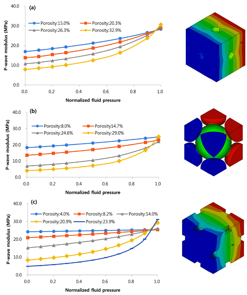
- For all types of RVEs, p-wave modulus becomes higher as fluid pressure increases (Fig. 4). As the active material compressed, the electrolyte resist the volume change by the amount of the bulk modulus of the fluid. Higher fluid pressure means larger load can be applied on the electrolyte, which results in higher modulus to the RVE model. It should be noted that the sensitivity of the fluid pressure to the modulus decreases as the porosity of all types of RVEs decreases.
- 4.2. Porosity of the graphite powder matrix
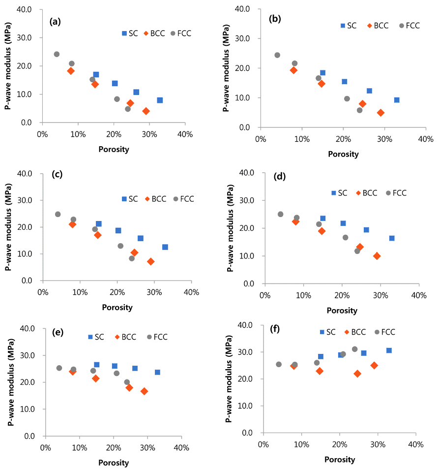
- The RVE analyses results were rearranged as the function of the porosity of the active material (Fig. 5). Pwave modulus of the active material decreases for all types of RVEs as the porosity increases. Small fluid pressure means the load bearing capacity of the fluid is small compare to the solid matrix. Therefore, increase of the porosity makes the overall structure weak, since the volume ratio of the solid structure decreases. But for high fluid pressure (α > 0.9), modulus of the active material slightly increases as the porosity increases. As the fluid in the active materials plays a major role in the load bearing capacity, decrease of the load bearing capacity of the solid is neglected (α = 0.9), or somewhat strengthen the overall RVE structures (α = 1.0). Zero fluid pressure condition means that the fluid cannot bear any load applied to the RVE. Thus, one can compare the strength of the 3 RVEs with only graphite powder matrix considered (SC > BCC ≥ FCC).
- 4.3. Specific surface area and electric performance
- Higher surface area of the graphite powder matrix is preferred to active surface area, since a higher surface allows short diffusion paths for lithium ions between the graphite powders; this facilitates fast charge and discharge rate and improves the capacity of the battery [12]. But the active materials with high surface area is predicted to have weak mechanical properties (Fig. 6). It will also result in low speed of sound of the active material (eqn.10), which goes to low natural frequency of the LIB. This is not recommendable for the EV battery design since the durability against dynamic loads (mechanical shock and vibration) can be decreased.
4. Analysis Results
P-wave modulus vs. Normalized fluid pressure of the 3 types RVEs: (a) SC structure based RVE; (b) BCC structure based RVE (c); and FCC structure based RVE.
P-wave modulus vs. porosity of the 3 types of RVEs for different normalized fluid pressure (α): (a) α = 0.0; (b) α = 0.2; (c) α = 0.5; (d) α = 0.7; (e) α = 0.9; and (f) α = 1.0.
- In this study, a finite element analysis approach was developed to predict the fluid-structure interaction behavior of anode active materials for LIBs. The major conclusions reached were as follows:
1) 3 difference types of RVEs show similar mechanical properties based on the porosity of the graphite powder matrix. Especially, sensitivity of the fluid pressure to the P-wave modulus decreases as the porosity of all types of RVEs decreases.
2) To design a LIB with high electric performance, high surface area of the active material is required. This results in low mechanical properties of the LIB, which goes to poor structural durability against dynamic loads.
- The results obtained provide useful information for both LIB cell developers at the concept design stage and engineers of electric vehicles who want to predict the mechanical safety of a battery pack.
5. Conclusions
- 1. J. W. Choi, J. O. Mun and D. M. Kang: Korea, KR 003263 (2014). .
- 2. A. Thaler, and D. Watzenig: Automotive Engineering - Simulation and Validation Methods, Springer, Berlin (2014) 19. .
- 3. T. Smit, J. Huyghe and S. Cowin: J. Biomech., 35 (2002) 829. .ArticlePubMed
- 4. C. Vinci, J. Renner and H. Steeb: Water Resour. Res., 50 (2014) 1616. .Article
- 5. J. Rubino, C. Ravazzoli and J. Santos: Geophysics, 74 (2009) 1. .Article
- 6. W. Lai, M. Ali and J. Pan: J. Power Sources, 248 (2014) 789. .Article
- 7. F. Maroni, S. Gabrielli, A. Palmieri, E. Marcantoni, F. Croce and F. Nobili: J. Power Sources, 332 (2016) 79. .Article
- 8. F. Otero, S. Oller, X. Martinez and O. Salomon: Compos. Struct., 122 (2015) 405. .Article
- 9. W. Lai, M. Ali and J. Pan: J. Power Sources, 1 (2014) 609. .Article
- 10. G. Gor, J. Cannarella, J. Prevost and C. Arnold: J. Electrochem Soc., 161 (2014) 3065. .Article
- 11. A. Shabana: Vibration of Discrete and Continuous System, Springer, Berlin (1996) 106. .Article
- 12. V. Agubra and J. Fergus: Materials, 6 (2013) 1310..ArticlePubMedPMC
Figure & Data
References
Citations


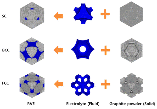


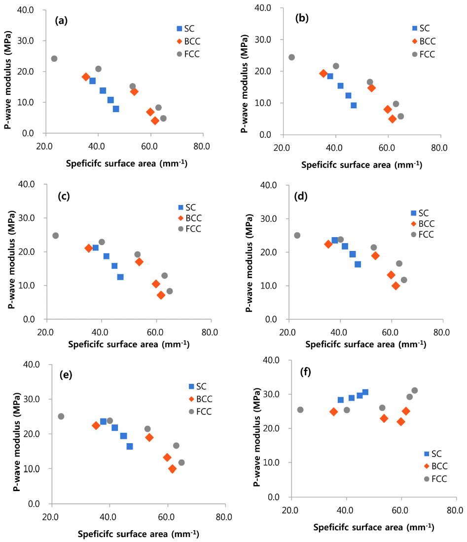
Fig. 1
Fig. 2
Fig. 3
Fig. 4
Fig. 5
Fig. 6
| Material properties | Value | unit | Component |
|---|---|---|---|
|
|
|||
| Elastic modulus | 20 | MPa | Solid matrix |
| Density | 558 | kg/m3 | Solid matrix |
| Poisson’s ratio | 0.3 | - | Solid matrix |
| Speed of sound | 1414 | m/s | Electrolyte |
| Viscosity | 4.2 | MPa·s | Electrolyte |
Table 1
TOP
 KPMI
KPMI



 Cite this Article


