Articles
- Page Path
- HOME > J Korean Powder Metall Inst > Volume 24(4); 2017 > Article
-
ARTICLE
- The Synthesis and Photocatalytic activity of Carbon Nanotube-mixed TiO2 Nanotubes
- Chun Woong Park, Young Do Kim, Tohru Sekinoa, Se Hoon Kimb,*
-
Journal of Korean Powder Metallurgy Institute 2017;24(4):279-284.
DOI: https://doi.org/10.4150/KPMI.2017.24.4.279
Published online: July 31, 2017
Department of Materials Science and Engineering, Hanyang University, Seoul 04763, Republic of Korea
a The Institute of Scientific and Industrial Research, Osaka University, Mihogaoka 8-1, Ibaraki, Osaka 567-0047, Japan
b Materials Convergence & Design R&D Center, KATECH, 303 Poongsero, Poongsemyeon, Cheonan-si, Chungnam 31214, Republic of Korea
- *Corresponding Author: Se Hoon Kim, +82-41-559-3377, +82-41-559-3288, shkim@katech.re.kr
• Received: August 11, 2017 • Revised: August 21, 2017 • Accepted: August 22, 2017
© The Korean Powder Metallurgy Institute. All rights reserved.
- 1,145 Views
- 11 Download
- 1 Crossref
Abstract
- The formation mechanism and photocatalytic properties of a multiwalled carbon nanotube (MWCNT)/TiO2- based nanotube (TNTs) composite are investigated. The CNT/TNT composite is synthesized via a solution chemical route. It is confirmed that this 1-D nanotube composite has a core-shell nanotubular structure, where the TNT surrounds the CNT core. The photocatalytic activity investigated based on the methylene blue degradation test is superior to that of with pure TNT. The CNTs play two important roles in enhancing the photocatalytic activity. One is to act as a template to form the core-shell structure while titanate nanosheets are converted into nanotubes. The other is to act as an electron reservoir that facilitates charge separation and electron transfer from the TNT, thus decreasing the electronhole recombination efficiency.
- Titanium dioxide (TiO2) has unique physicochemical properties and then is widely investigated and used in many applications such as photocatalyst, Li-battery anode, dye-sensitized solar cell, antimicrobial coating, gas sensor, hydrogen storage, and biocompatible surface due to their high photocatalytic activity, natural abundance, chemical stability and nontoxicity [1, 2].
- Recently, TiO2-based nanotubes have attracted much attention due to the unique combination of physicochemical properties and low-dimensional nanostructures of TiO2 [3-5]. It has been prepared by replica- or template- assisted methods [5-9], templateless methods via a solution chemical synthesis [4, 6, 9-11], hydrothermal treatment [12, 13], and electrochemical anodic oxidation [14-16]. Among these, the solution chemical method, first reported by Kasuga et al. [4, 10], has the advantage of simple and low-cost fabrication of nanostructured crystallite materials. This synthesis easily allows to obtain TNTs with diameter of around 10 nm and to hybridize with other materials by relatively low-temperature processing which is based on the refluxing TiO2 powder in the high concentration alkaline solution (10~20 M) at 100-150°C. On the other hand, carbon nanotubes (CNTs) [17, 18] are also well known one-dimensional (1-D) nanomaterials, and that not only can they facilitate the electron- hole separation but also enhance the light absorption of the photocatalysts [12, 19], hence the synthesis of CNT-TiO2 nanoparticles are reported in some studies [13, 20]. In spite of unique characteristics of these two 1-D nanomaterials, as far as the authors know, there is no report on the synthesis and characterization of highly structure-controlled hybrids of TNT and CNT with coreshell morphology.
- In this study, we demonstrate a simple route to fabricate the 1-D nanostructured core-shell composite of CNT and TNT for enhancing the photocatalytic properties. This composite was synthesized via the solution chemical synthesis route. The microstructural characteristics of as-synthesized CNTs and TNTs composite, compared with pure TNTs, were investigated by several analytical techniques such as X-ray diffraction, scanning and transmission electron microscopy, thermo-gravimetric analysis, Raman spectroscopy, and the formation mechanism of as-prepared composite was discussed. The enhanced photocatalytic activity of CNT and TNT composite was also discussed by the results of adsorption and degradation of methylene blue.
Introduction
- The commercial anatase-phase TiO2 (Wako pure chemical, Japan, 99%) powder and MWCNTs (Sigma-Aldrich, USA, OD=10-20 nm, ID=5-10 nm, >95%) were used as starting materials. Next, MWCNT-TNT composite, hereafter designated CNT-TNT, which had molar ratio of 5% of CNT to TNT was synthesized via a soft hydrothermal route. CNTs were dispersed in distilled (DI) water for 30 min by ultrasonic and magnetic stirring to achieve homogeneous dispersions. TiO2 powder was added to the CNT dispersions, and then NaOH was added to reach 10M NaOH solution, and the mixture was refluxed at control temperature of 135°C for 24 h. The resultant product was washed with DI water and was treated 0.1M HCl. The treated product was washed again with DI water until the solution conductivity reached below 10 μS/cm. Finally, the synthesized powder was dried in an oven at 70°C for 48 h.
- The phase analysis of synthesized samples was conducted by powder X-ray diffractometer (XRD, D8 Advance, Bruker AXS GmbH, Karlsruhe, Germany) using Cu Kα radiation. Field emission scanning electron microscopy (FESEM) images were acquired using Nova NanoSEM 450 (FEI, Hillsboro, USA). Microstructure observation and composition analysis were performed by a transmission electron microscopy (TEM, JEM-2100F, JEOL, Japan) with an accelerating voltage of 200 kV equipped with an energy dispersive spectroscopy (EDS). The thermogravimetric (TG, TG-DTA2000SA, MAC Science, Japan) analysis was performed under a heating rate of 1°C/min up to 800°C with Air flow of 1 l/min. RAMAN spectra of samples were acquired by NRS-2000A (JASCO, Japan). The adsorption and degradation properties of TNT and CNT-TNT samples were analyzed using methylene blue (MB, Wako Pure Chemical Industries, Japan). 20 mg of each sample was dispersed in 100 ml of 10 mg/l MB solution. The adsorption was measured for 4 h in the dark, and then the degradation was evaluated in the UV light irradiation (mercury–xenon lamp with a center wavelength of 365 nm, UVF-204S, SAN-EI Electric, Japan) at room temperature. The MB solution was analyzed with UV-vis spectrophotometer (UV mini-1240, Shimadzu, Japan) by measuring the absorption band of 663 nm.
Materials and Methods
- The solution chemical synthesis process successfully provided dark grayish powdery products. As shown in Fig. 1, FESEM observation was performed to confirm the morphologies of TNT and CNT-TNT samples. Fig. 1(a) shows a typical morphology of as-synthesized TNT sample. The nanotubes were bundled each other from several tens to several hundreds. Their outer diameter was approximately 10 nm and length was below 1 μm as is well-known. Contrastively, nanotubes of CNT-TNT composite were well-separated each other as presented in Fig. 1(b). They had outer diameter of 20~40 nm and maximum length of several micrometers. In case of the adding CNTs, the specific surface area was presumed to be slightly decreased to about quarter because the diameter of nanotubes was increased from 10 nm to more than 20 nm. It could be inferred that CNTs affected to the morphology of TNTs during the alkaline hydrothermal synthesis. However, CNT could not be detected easily through FESEM observation.
- Fig. 2 shows the XRD patterns of the TiO2 powder as raw material and the TNTs synthesized with and without CNTs. Whereas the raw material TiO2 powder was shown as an anatase phase (JCPDS 21-1272), the as-synthesized TNT and CNT-TNT composite did not exhibited clear and sharp crystallite peaks. In fact, it was known that pure TNT synthesized by an alkaline hydrothermal route was formed to H2TinO2n+1 or NaxH2-xTinO2n+1 (n=3, 4) [11]. In this study, observed diffraction peaks of the pure TNT at around 2θ of 10°, 24.5° and 48.5° corresponding to the (200), (110), and (020) planes were in good agreement with the monoclinic H2Ti4O9·H2O (JCPDS 36-655) having four edge-sharing TiO6 octahedra in the unit cell. On the other hand, the XRD pattern of CNT-TNT sample (2θ ~ 8.4°, 10.6°, 12.4°, 25° and 48.5° corresponding to (001), (200), (201), (110), and (020) planes, respectively) seemed to be monoclinic H2Ti3O7·nH2O because two peaks of (001) and (201) planes were more similar to pattern of the H2Ti3O7 (JCPDS 47-561) having three edge-sharing TiO6 octahedra. The typical CNT peak that should exist around 25° could not be confirmed due to its small amount and peak overlap with TNT peak of (110) plane, and some peaks which were indexed to (001), (200), and (201) planes, were shifted to lower angles as compared with an anhydrous H2Ti3O7. It is well-known that the interlayer spacing of TNT is expanded with increasing the amount of adsorbed water because this adsorbed H2O exists in the one-dimensional tunnel and skeletal crystal structure of nanotubes [21]. Thus, it was speculated that the peaks of (001), (200), and (201) planes were shifted due to adsorbed H2O of sample.
- To analyze more detail, TG analysis was conducted Fig. 3 shows the TG curves of TNT and CNT-TNT samples. Some steps were observed at 30-150, 150-250, 250- 400°C for TNT and CNT-TNT, and at 550-700°C only for CNT-TNT. The first step up to 150°C was desorption of H2O, which was existed in interlayer space of nanotube wall. The weight loss of CNT-TNT composite in this step was approximately 5.1% corresponding to 0.78H2O in H2Ti3O7·nH2O. Pure TNT sample had the weight loss of 5.3% that was equivalent to one mole of H2O in H2Ti4O9·nH2O. The weight losses of second and third steps from 150 to 450°C meant that titanate (H2TinO2n+ 1) was changed to TiO2 through a dehydration. In these steps, the weight losses were approximately 5.4 and 6.6% for pure TNT and CNT-TNT samples, respectively. Also, the calculated dehydration amounts of H2Ti4O9 and H2Ti3O7 are 5.3 and 6.9%, respectively. From the results of XRD and TGA, it was considered that TNT and CNTTNT were formed as H2Ti4O9·H2O and H2Ti3O7·0.78H2O each. Moreover, the weight loss at 550-700°C for CNTTNTs was confirmed to be occurred by burning the MWCNTs corresponding to 5mol.%.
- Fig. 4 shows the RAMAN spectra of TNT and CNT-TNT samples. The RAMAN band at 190 cm-1 was attributed to the anatase TiO2 mode [11] and bands at 275 cm-1, 448 cm-1, 670 cm-1, 840 cm-1 were generally assigned to the TNTs [2, 22, 23]. It was reported that the features at 275 cm-1, 448 cm-1, 670 cm-1 were originated from Ti-O-Ti vibration and the band around 840 cm-1 with a broad and weak intensity was related to Ti-O-H vibration [23, 24]. However, the origin of TNTs bands is still not revealed clearly. The inset in Fig. 4 shows the D-band at 1350 cm-1 and Gband at 1580 cm-1 of CNT for the CNT-TNT composite, showing CNT could remain without any serious damage during the high concentration alkali treatment.
- To reveal the formation mechanism of CNT-TNT composite, FESEM and TEM observations were conducted. Although the formation mechanism of pure TNT in NaOH aqueous solution has been argued between some researchers till now, many researchers agree that the titanate nanosheets are formed and then are rolled to nanotubes [25-28]. FESEM image of the CNT-TNT sample which was taken during an alkaline hydrothermal synthesis was shown in Fig. 5(a). It can be confirmed that the titanate sheet-like products wrapped around the CNTs before rolling to titanate nanotubes. Fig. 5(b) shows TEM image of the as-synthesized CNT-TNT sample. The result of TEM-EDS line-scanning revealed that the CNT and TNT were consisted by the core-shell nanotubular structure, where the TNT shell surrounded the CNT core. It could be confirmed that the inner and outer diameters of TNT which had the tubular structure were ~20 nm and ~25 nm, respectively. The diameter of TNT on CNT-TNT composite was increased compared with that of the pure TNT sample which had the outer diameter of ~10 nm. According to the formation mechanism of TNT, it was consequently speculated that the increment of diameter was because while titanate nanosheet was formed to nanotube, this nanosheet wrapped around the CNT template having a diameter of ~10 nm, resulting in forming the core-shell structure.
- To evaluate the photocatalytic activity of synthesized CNT-TNT composite, the MB removal test was performed under the dark and UV light irradiation conditions. Fig. 6 depicts the adsorption and degradation properties of MB by TNT, and CNT-TNT samples. The amount of adsorbed MB by CNT-TNT was slightly lower than that by TNT. The lower amount of adsorbed MB on CNT-TNT sample could be ascribed to the decrease to about quarter of the specific surface area of TNT due to increasing the diameter and wall thickness of synthesized nanotubes as mentioned before. However, the degradation rate of MB by CNT-TNT sample under UV light irradiation after 4 h was dramatically higher than that by TNT. This superiority of CNT-TNT was considered that CNT acted as a reservoir to trap electrons emitted from TNT during the photocatalysis process, and thereby the electron-hole pair recombination could efficiently be suppressed, resulted in improvement of the photocatalytic activity [12, 19].
- To enhance photocatalytic properties of TiO2, many researches have been performed to load noble metal nanoparticles (NPs) such as Pt on TiO2 surface to facilitate the co-catalytic effect of the metal NPs [29, 30]. Recently, Pt NPs loaded TNT has also attracted much attention due to their potential as high-performance catalyst [31-35]. In the case of metal (Pt) NPs loaded TiO2, it is argued that photocatalytic degradation of organic molecules in TiO2 surface is promoted by the reduction and oxidation reaction by various radicals such as O2•-, OH• and so on which are generated by the photogenerated electrons and holes [35, 36]. The Pt NPs plays a major role in realizing charge separation to hold electrons while the TiO2 acts individual molecular adsorption as well as reaction site by providing photogenerated holes for radical formation as h+ + OH- → OH• [36]. In the present CNT-TNT composite, CNT core might accumulate electrons and TNT shell sufficiently acts as reaction site of MB degradation. In this regard, TNT surface can fully utilized for this sequence due to the core-shell structure. This seems to be the similar effect that was pointed out for the site-selective loading of Pt into inside of TNTs, which exhibited better photocatalytic activity for oxidation of acetaldehyde gas than those of Pt NPs loaded on the outer surface of TNTs [31]. However, it is considered that CNT might be more desirable as electron accumulation agent because of higher electronegativity of carbon than platinum. These facts hence imply us that the core-shell CNT-TNT has suitable nanostructure with the enhanced photocatalytic activity.
Results and Discussion
Fig. 4
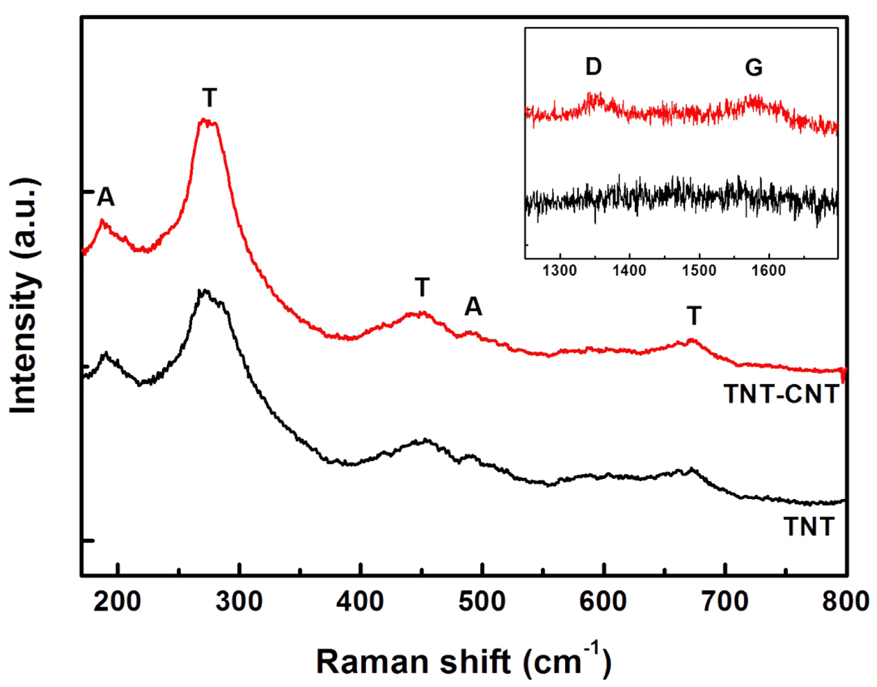
Raman spectra of TNT and CNT-TNT composite. (Inset) D and G bands of CNT for CNT-TNT composite.

Fig. 5
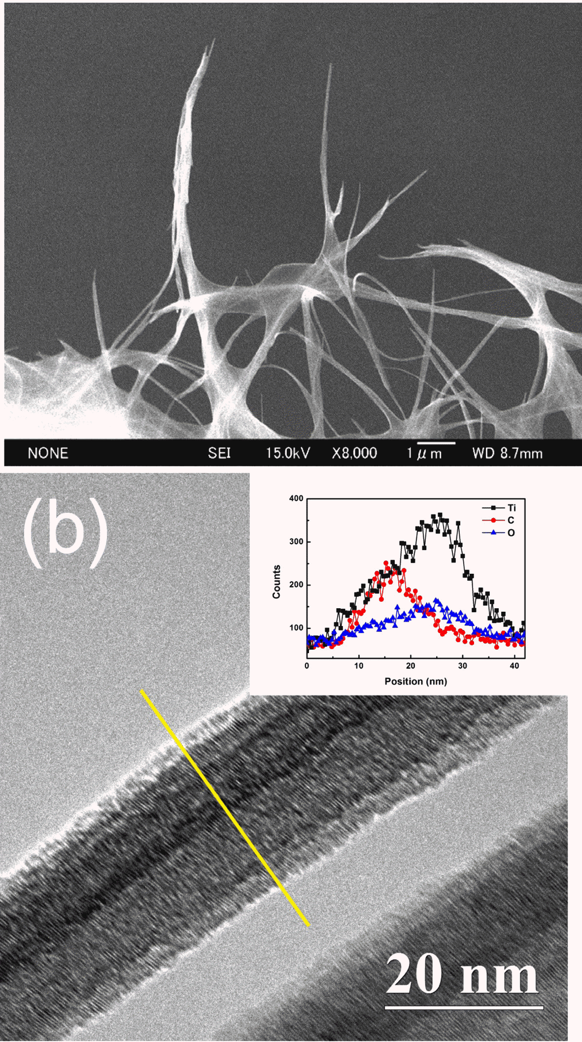
FESEM and TEM images of CNT-TNT composite; (a) during an alkaline hydrothermal synthesis and (b) assynthesized. (Inset) Line profile of the TEM-EDS corresponding to yellow line in (b).

- One dimensional CNT-TNT composite was successfully synthesized via the solution chemical route. FESEM and HRTEM results showed that CNT-TNT composite was formed by the core-shell nanotubular structure with outer diameter of 20~40 nm and maximum length of several micrometers, where the TNT surrounded the CNT core. It was speculated that the titanate nanosheet, composed by H2Ti3O7·0.78H2O, might roll-up to the CNT template.
- In the photocatalytic activity of samples, although the MB adsorption property of CNT-TNT was slightly decreased, as compared with that of pure TNT, the MB degradation under UV light irradiation was significantly increased due to the appropriate nanoarchitecture and resultant function sharing of CNT core and TNT shell. It was thus considered that such a low-dimensional coreshell nanotube consisting of semiconductor oxide (TNT) and conductive carbon (CNT) may exhibit better photo- catalytic activity as CNT played a role in suppressing the electron-hole pair recombination of photocatalysts.
Conclusions
-
Acknowledgements
- This research was supported in part by the JSPS under the Grant-in-Aid for JSPS Fellows (No.23-01332) and under the Grants-in-Aid for Scientific Research (A) (No. 22241017). This research was also supported in Basic Science Research Program through the National Research Foundation of Korea (NRF) funded by the Ministry of Education (NRF-2016R1A6A1A03013422).
Acknowledgments
- 1. A. Fujishima and K. Honda: Nature., (1972) 238 37.ArticlePDF
- 2. D.V. Bavykin, J.M. Friedrich and F.C. Walsh: Adv. Mater., (2006) 18 2807.Article
- 3. P. Hoyer: Langmuir., (1996) 12 1411.Article
- 4. T. Kasuga, M. Hiramatsu, A. Hoson, T. Sekino and K. Niihara: Langmuir., (1998) 14 3160.Article
- 5. H. Imai, Y. Takei, K. Shimizu, M. Matsuda and H. Hirashima: J. Mater. Chem., (1999) 9 2971.Article
- 6. T. Sekino, T. Okamoto, T. Kasuga, T. Kusunose, T. Nakayama and K. Niihara: Key Eng. Mater., (2006) 317-318 251.Article
- 7. A. Michailowski, D. AlMawlawi, G.S. Cheng and M. Moskovits: Chem. Phys. Lett., (2001) 349 1.Article
- 8. S.M. Liu, L.M. Gan, L.H. Liu, W.D. Zhang and H.C. Zeng: Chem. Mater., (2002) 14 1391.Article
- 9. D. Eder and A.H. Windle: Adv. Mater., (2008) 20 1787.Article
- 10. T. Kasuga, M. Hiramatsu, A. Hoson, T. Sekino and K. Niihara: Adv. Mater., (1999) 11 1307.Article
- 11. I. Tacchini, A. Anson-Casaos, Y. Yu, M. T. Martinez and M. Lira-Cantu: Mater. Sci. Eng. B., (2012) 177 19.Article
- 12. W. Wang, C. Lu, Y. Ni, M. Su and Z. Xu: Mater. Lett., (2012) 79 11.Article
- 13. T.T. Duong, Q.D. Nguyen, S.K. Hong, D. Kim, S.G. Yoon and T.H. Pham: Adv. Mater., (2011) 23 5557.Article
- 14. R.P. Antony, T. Mathews, A. Dasgupta, S. Dash, A.K. Tyagi and B. Raj: J. Solid State Chem., (2011) 184 624.Article
- 15. L. Wang, X. Wu and S. Zhang: Appl. Mech. Mater., (2012) 130-134 1281.Article
- 16. D. Gong, C.A. Grimes, O.K. Varghese, W. Hu, R.S. Singh, Z. Chen and E.C. Dickey: J. Mater. Res., (2001) 16 3331.Article
- 17. S. Iijima: Nature., (1991) 354 56.ArticlePDF
- 18. V. Pifferi, G. Facchinetti, A. Villa, L. Prati and L. Falciola: Catal. Today., (2015) 249 265.Article
- 19. Y. Zhang, Z.R. Tang, X. Fu and Y.J. Xu: ACS Nano., (2010) 4 7303.Article
- 20. H. Yu, X. Quan, S. Chen and H. Zhao: J. Phys. Chem. C., (2007) 111 12987.Article
- 21. S. Suzuki and M. Miyayama: J. Ceram. Soc. Jpn., (2010) 118 1154.Article
- 22. M. Hodos, E. Horvath, H. Haspel, A. Kukovecz, Z. Konya and I. Kiricsi: Chem. Phys. Lett., (2004) 399 512.Article
- 23. L. Qian, Z.L. Du, S.Y. Yang and Z.S. Jin: J. Mol. Struct., (2005) 749 103.Article
- 24. S.H. Byeon, S.O. Lee and H. Kim: J. Solid State Chem., (1997) 130 110.Article
- 25. G.H. Du, Q. Chen, R.C. Che, Z.Y. Yuan and L.M. Peng: Appl. Phys. Lett., (2001) 79 3702.ArticlePDF
- 26. D.V. Bavykin, V.N. Parmon, A.A. Lapkin and F.C. Walsh: J. Mater. Chem., (2004) 14 3370.Article
- 27. A. Kukovecz, M. Hodos, E. Horvath, G. Radnoczi, Z. Konya and I. Kiricsi: J. Phys. Chem. B., (2005) 109 17781.Article
- 28. Y.Q. Wang, G.Q. Hu, X.F. Duan, H.L. Sun and Q.K. Xue: Chem. Phys. Lett., (2002) 365 427.Article
- 29. E. Borgarello, J. Kiwi, M. Grätzel, E. Peliuetti and M. Visca: J. Am. Chem. Soc., (1982) 104 2996.Article
- 30. K.E. Karakitsou and X.E. Verykios: J. Phys. Chem., (1993) 97 1184.Article
- 31. K. Nishijima, T. Fukahori, N. Murakami, T. Kamai, T. Tsubota and T. Ohno: Appl. Catal. A., (2008) 337 105.Article
- 32. K.P. Yu, W.Y. Yu, M.C. Kuo, Y.C. Liou and S.H. Chien: Appl. Catal. B., (2008) 84 112.Article
- 33. A.V. Grigorieva, E.A. Goodilin, L.E. Derlyukova, T.A. Anufrieva, A.B. Tarasov, Y.A. Dobrovolskii and Y.D. Tretyakov: Appl. Catal. A., (2009) 362 20.Article
- 34. Q. Zhao, M. Li, J. Chu, T. Jiang and H. Yin: Appl. Surf. Sci., (2009) 255 3773.Article
- 35. D.J. Park, T. Sekino, S. Tsukuda and S.I. Tanaka: J. Ceram. Soc. Jpn., (2012) 120 307.Article
- 36. A. Houas, H. Lachheb, M. Ksibi, E. Elaloui, C. Guillard and J. M. Herrmann: Herrmann: Appl. Cat. B: Environ., (2001) 31 145.
Figure & Data
References
Citations
Citations to this article as recorded by 

- Low-Dimensional Carbon and Titania Nanotube Composites via a Solution Chemical Process and Their Nanostructural and Electrical Properties for Electrochemical Devices
Sunghun Eom, Sung Hun Cho, Tomoyo Goto, Myoung Pyo Chun, Tohru Sekino
ACS Applied Nano Materials.2019; 2(10): 6230. CrossRef
The Synthesis and Photocatalytic activity of Carbon Nanotube-mixed TiO2 Nanotubes
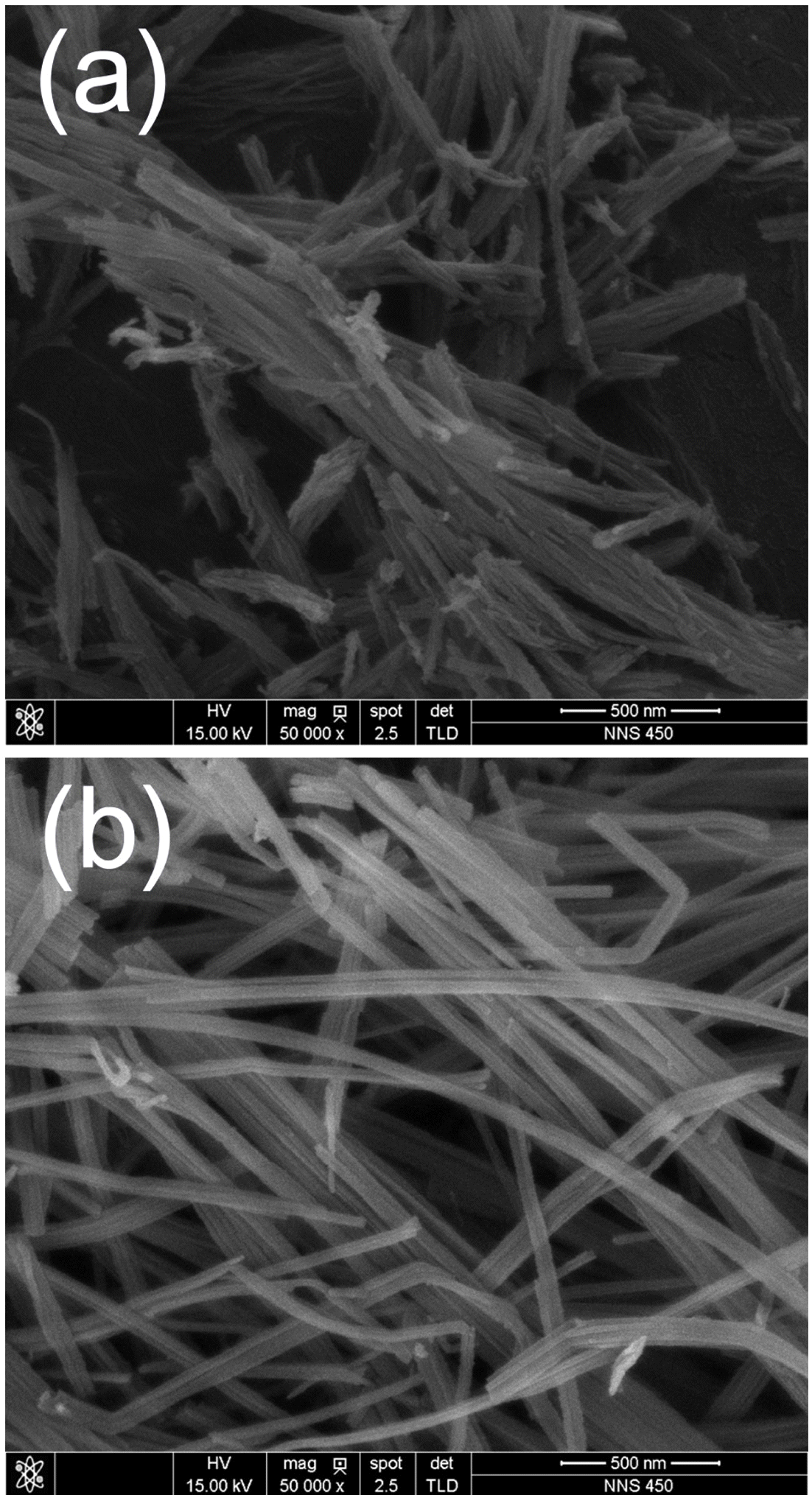
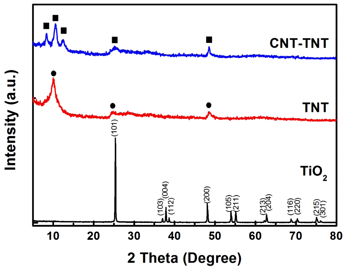
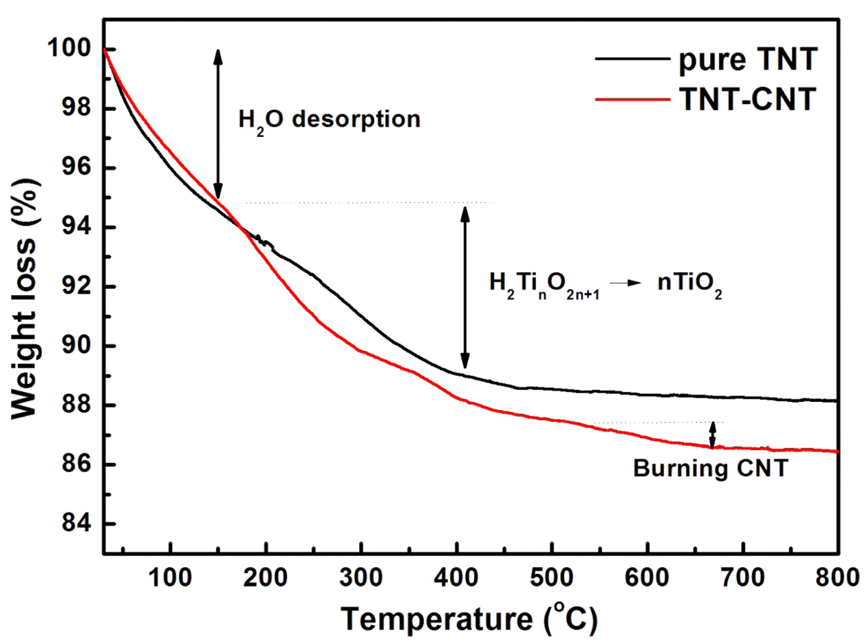


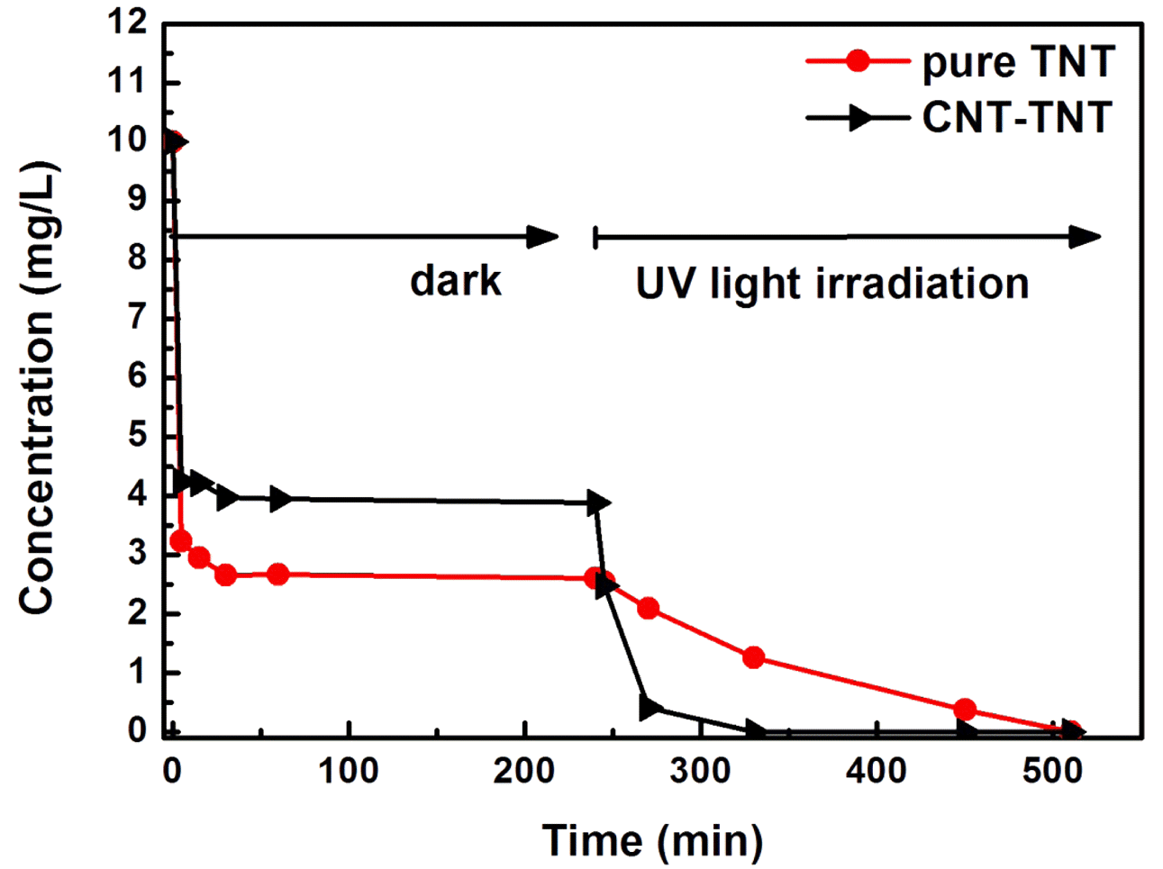
Fig. 1
FE-SEM images of (a) as-synthesized pure TNT and (b) CNT-TNT composite.
Fig. 2
XRD patterns of raw TiO2, as-synthesized TNT and CNT-TNT composite.
Fig. 3
Thermogravimetric (TG) curves of TNT and CNTTNT composite.
Fig. 4
Raman spectra of TNT and CNT-TNT composite. (Inset) D and G bands of CNT for CNT-TNT composite.
Fig. 5
FESEM and TEM images of CNT-TNT composite; (a) during an alkaline hydrothermal synthesis and (b) assynthesized. (Inset) Line profile of the TEM-EDS corresponding to yellow line in (b).
Fig. 6
Adsorption and degradation of MB for TNT and CNT-TNT under dark and UV light irradiation.
Fig. 1
Fig. 2
Fig. 3
Fig. 4
Fig. 5
Fig. 6
The Synthesis and Photocatalytic activity of Carbon Nanotube-mixed TiO2 Nanotubes
TOP
 KPMI
KPMI


 Cite this Article


