Articles
- Page Path
- HOME > J Korean Powder Metall Inst > Volume 24(3); 2017 > Article
-
ARTICLE
- Optimization of Process Condition for Fe Nano Powder Injection Molding
- Joo Won Oh, Won Sik Leea, Seong Jin Park*
-
Journal of Korean Powder Metallurgy Institute 2017;24(3):223-228.
DOI: https://doi.org/10.4150/KPMI.2017.24.3.223
Published online: May 31, 2017
Department of Mechanical Engineering, Pohang University of Science and Technology (POSTECH),77 Cheongam-Ro, Nam-Gu, Pohang, Gyeongbuk 37673, Republic of Korea
a The Advanced Process and Materials R&D Group, Korea Institute of Industrial Technology, 156 Gaetbeol-ro, Yeonsu-gu, Incheon 21999, Republic of Korea
- *Corresponding Author: Seong Jin Park, +82-54-279-2182, +82-54-279-5899, sjpark87@postech.ac.kr
• Received: May 29, 2017 • Revised: June 13, 2017 • Accepted: June 15, 2017
© The Korean Powder Metallurgy Institute. All rights reserved.
- 1,105 Views
- 2 Download
- 3 Crossref
Abstract
- Nanopowders provide better details for micro features and surface finish in powder injection molding processes. However, the small size of such powders induces processing challenges, such as low solid loading, high feedstock viscosity, difficulty in debinding, and distinctive sintering behavior. Therefore, the optimization of process conditions for nanopowder injection molding is essential, and it should be carefully performed. In this study, the powder injection molding process for Fe nanopowder has been optimized. The feedstock has been formulated using commercially available Fe nanopowder and a wax-based binder system. The optimal solid loading has been determined from the critical solid loading, measured by a torque rheometer. The homogeneously mixed feedstock is injected as a cylindrical green body, and solvent and thermal debinding conditions are determined by observing the weight change of the sample. The influence of the sintering temperature and holding time on the density has also been investigated. Thereafter, the Vickers hardness and grain size of the sintered samples have been measured to optimize the sintering conditions.
- Powder injection molding (PIM) is a combined technique of traditional powder metallurgy and plastic injection molding [1]. Traditional powder metallurgy process has intrinsic shaping limitations due to uniaxial compaction. Whereas, PIM has high design flexibility because it uses injection molding technique to form a green body. Therefore, PIM is one of the most appropriate manufacturing processes for 3-dimensional complex parts [2]. PIM is also a net shaping technique with tight tolerance [1]. Such merits of PIM can be good advantages for microfabrication [3]. PIM process consists of 4 steps, which are mixing, injection molding, debinding and sintering. In the mixing step, powder and molten binders are mixed to formulate feedstock. Thereafter, the feedstock is injected into a mold cavity, and green body is fabricated. Before sintering, the binders in the green body are removed with the debinding process, and densification occurs by thermally activated diffusion during sintering.
- Particle size is an important factor in PIM process. It is known that the minimum feature size has to be 10 times larger than mean particle size [3]. Thus, nano powder needs to be used in the process for fabrication of micro features. However, due to the small size of nano powder, various challenges appear in nano PIM process [4]. Large surface area of nano powder leads to low packing density and critical solids loading [5]. Its feedstock also shows relatively high viscosity. Debinding methods for coarse powder cannot be applied to nano powder because it enhances the difficulties of binder removal [6]. Narrow interparticle space hinders debinding process and may result in defects. Therefore, a slow heating rate should be applied, and additional processes, such as solvent debinding, are required to minimize the defects. Unique sintering behavior, originated from the large surface energy of nano powder, needs to be considered as well. Thus, process conditions for each step should be carefully deter- mined and optimized for nano PIM process.
- In this research, PIM process for Fe nano powder has been developed and optimized with experimental approaches. A feedstock was fabricated by mixing the nano powder and a wax-based binder system. Torque rheometer test was conducted to determine the optimal solids loading. The debinding behavior of the feedstock was observed, and thermal decomposition activation energy was calculated with TGA experimental data. Sintered density change depending on sintering condition was analyzed, and grain size and Vickers hardness were measured.
Introduction
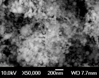
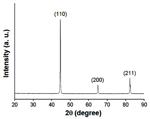
- Commercially available 100 nm Fe powder (Nano technology, Korea) was used in the study. The powder was fabricated by pulsed wire evaporation method. The morphology of the powder was observed by FE-SEM (JEOL, JSM-7401F), and the image is shown in Fig. 1. Fig. 2 is the XRD pattern of nano powder. The result indicated the powder was α phase Fe. Apparent density and tap density were measured with tap density volumeter (Bettersize Instruments Ltd., BT-300), and pycnometer density was measured by automatic helium pycnometer (Micromeritics, Accupyc 1330). The results of powder characterization are listed in Table 1. A wax-based binder system was used in the study to formulate the feedstock. The binder system consisted of 55 wt. % paraffin wax (PW), 25 wt. % polypropylene (PP), 15 wt. % polyethylene (PE) and 5 wt. % stearic acid (SA). PW was a major binder, and PP and PE were backbone polymers. SA was a surfactant to bridge between the binders and the powder.
- Solids loading is the volumetric ratio of powder in a feedstock. The critical solids loading was measured with torque rheometer (Thermo scientific, HAAKE PolyLab QC Lab Mixer) to determine the optimal solids loading. Some fixed amount of nano powder and the binder system were mixed in mixing chamber at 150°C and 150 rpm. The powder was added to increase the solids loading of the feedstock in the chamber, and the change of mixing torque was observed. Feedstock formulation was conducted with a twin-screw extruder at 160°C and 30 rpm. To obtain homogeneous feedstock, mixing procedure was repeated for several times. The feedstock was shaped via injection molding machine (Sodick, TR30EH) under 25MPa at 160°C. Cylindrical green bodies were fabricated without any visible defects, and their dimension was 8 mm in diameter and 13 mm in height. Both of solvent and thermal debinding process were applied to remove the binder system from the green body. Firstly, PW and SA were dissolved by 50°C n-hexane for 12 hours. Thereafter, residual binders were thermally decomposed in tube furnace (Kejia, KJ-1600G) in argon atmosphere. Thermal decomposition behavior of the feedstock was observed by TGA (METTLER TOLEDO, TGA/DSC 1) in argon atmosphere from 30 to 600°C to determine thermal debinding condition. As a result, two isothermal stages were set at 250 and 450°C for 2 hours. The heating rate was also determined as 1°C/min because some defects were generated in debound samples with faster heating rate than 1°C/min. From TGA data, thermal decomposition activation energy of the feedstock was calculated as well. Sintering process was conducted by dilatometer (NETZSCH, DIL 402 C) with precise temperature control. The samples were sintered at various sintering temperatures from 600 to 1000°C with the heating rate of 10°C/min in hydrogen atmosphere. Holding time effect from 0 to 3 hours also analyzed. After sintering, the density of sintered samples was measured by archimedes densimeter (AND, GH-200D). Vickers hardness measurement was also performed with a microhardness tester (Future-tech, FM-700). Total 9 values were measured at random spots on the samples with 300 gf and a dwell time of 15s. The average grain size of each sample was measured after etching with 3% natal etchant. The area of about 100 grains at random points was measured with image analysis, and the diameter of each grain was calculated with the assumption of circular grain.
Experiments
Table 1
Characteristic of Fe nano powder
| Mean particle size | Apparent density | Tap density | Pycnometer density |
|---|---|---|---|
|
|
|||
| 100 nm | 1.44 g/cm3 | 2.25 g/cm3 | 7.42 g/cm3 |
- 3.1. Preparation of nano feedstock
- In order to prevent defects from samples, sound feedstock should be fabricated. One of the most important conditions for feedstock formulation is the determination of the optimal solids loading. If the solids loading is too high, an inhomogeneous feedstock will be formulated with very high viscosity [7]. Whereas, the feedstock with too low solids loading can cause shrinkage-related problems and collapse of the sample during the debinding process [1]. The critical solids loading of nano powder was measured by torque rheometer, and the result is exhibited in Fig. 3. As solids loading increased, mixing torque continuously increased in Fig. 3 (a). When solids loading exceeds its critical value, mixing torque rapidly increases because exposure of the powder surface due to lack of binders leads to high interparticle friction [8]. Fig. 3 (b) demonstrates solids loading dependency of stabilized mixing torque. It was obvious that the slope changed at the solids loading of 45 vol. %, and the result indicated the critical solids loading of nano powder was 45 vol. %. It is known that the optimal solids loading should be slightly less than the critical value for process flexibility [1]. Therefore, in this study, the optimal solids loading was determined as 44 vol. %.
- 3.2. Debinding behavior of nano feedstock
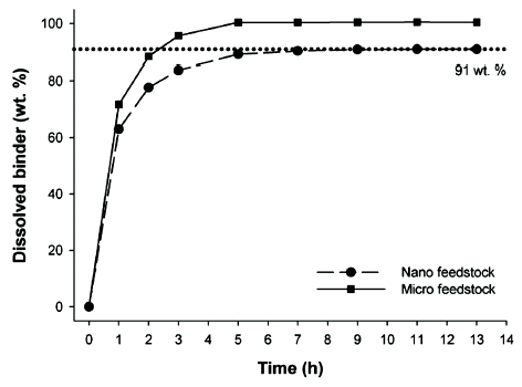
- The binder system has to be eliminated before sintering since remaining binder can be impurities in sintered samples [9]. In this study, two-step debinding process was performed to minimize possible defects. PW and SA were dissolved via solvent debinding, and Fig. 4 presents the weight ratio of dissolved binders depending on immersing time. As process time increased, more binders were dissolved, and the value converged into 91 wt. % after 11 hours. The figure also displays the result of micro feedstock fabricated with 3 μm Fe powder (BASF, Germany) and the same condition. Unlike nano feedstock, the binders in micro feedstock were completely removed within 5 hours. The result indicated that PW and SA required more time to be extracted from nano feedstock, and some amount of them would remain regardless of the time. This phenomenon was caused by the strong capillary force of nano powder, resulted from its small interparticle space [10]. Thermal decomposition behavior of the feedstock was also investigated with TGA experiment. The weight of the feedstock was measured from 30 to 600°C with 4 different heating rates, 2, 5, 10 and 15°C/min, and the result is illustrated in Fig. 5 (a). The thermal decomposition behavior could be divided into two sigmoidal shapes. During the first sigmoid, PW and SA were decomposed, and thereafter, PP and PE were decomposed in the second sigmoid. All binders were removed below 450°C with the heating rate of 2°C/ min, which was a similar condition to debinding process in the furnace. From the result, the optimal debinding condition was determined as a slow heating rate of 1°C/ min with 2 hours holding at 250 and 450°C. The former was for remaining PW and SA after solvent debinding, and the latter was to minimize the residual binders and pre-sintering for the handling of debound samples. Decomposition activation energy can be calculated from a first order reaction kinetics model and Kissinger method [5, 11] with the following equation:
- where, r is heating rate, and Tmax is the temperature where the maximum rate of weight loss occurred. Q, R and k0 represent the apparent decomposition activation energy, gas constant and specific rate constant for Arrhenius equation, respectively. From the equation, the activation energy, Q, could be calculated as a slope of ln [r/ Tmax2] vs. −1/RTmax. Fig. 5 (b) shows linear fitting results of 4 different heating rates. The decomposition activation energies of PW & SA and PP & PE were obtained as 91.4 and 190.5 kJ/mol, respectively, with good linearity. This good linearity of the points, obtained from different heating rate conditions, indicated the decomposition behavior of the binders was well measured without any external effects.
- 3.3. Sintered sample of nano feedstock
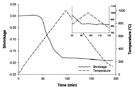
- The brown bodies were sintered at various temperatures from 600 to 1000°C, and the result is summarized in Table 2. As the temperature increased, the density tended to increase due to the activated thermal diffusion process. However, the density slightly decreased at 1000°C. It was caused by phase transformation around 910°C. As Fig. 6 displays, densification did not occur after phase transformation from ferrite to austenite, and expansion of the sample, observed during cooling step, decreased the density. As a result, the maximum sintered density was obtained at 900°C, and its relative density was about 0.93. Thus, the optimal sintering temperature was determined as 900°C. Holding time effect on the density was also studied in Table 3. The sintered density increased up to holding time of 2 hours, and the relative density reached near 0.98.
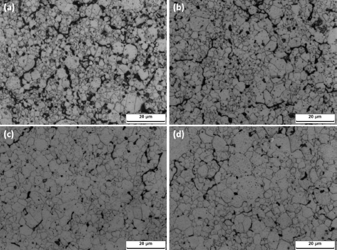
- Vickers hardness measurement was conducted to analyze the effect of holding time on hardness value, and the result is listed in Table 4. As the holding time increased, the hardness of the sample also increased because of higher density. However, it decreased with holding time of 3 hours despite the same density as 2 hours holding sample. This phenomenon can be explained with grain growth. The sample with smaller grain provides better mechanical properties because dense grain boundary prevents plastic deformation and crack propagation. Fig. 7 shows the microstructure of the samples after etching, and the average grain size is summarized in Table 4. The holding time had high influence on the grain size, and it almost proportionally increased to the holding time. As a result, in spite of higher density, 2 hours holding sample showed similar hardness value to an hour holding sample due to larger grain, and 3 hours holding sample had even lower value. From this observation, it can be concluded that the optimal sintering condition for nano feedstock was 900°C with 2 hours holding.
Results and Discussion
Fig. 3
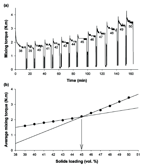
Mixing torque of nano feedstock in different solids loading conditions: (a) mixing torque and (b) average value of stabilized mixing torque.

Fig. 5
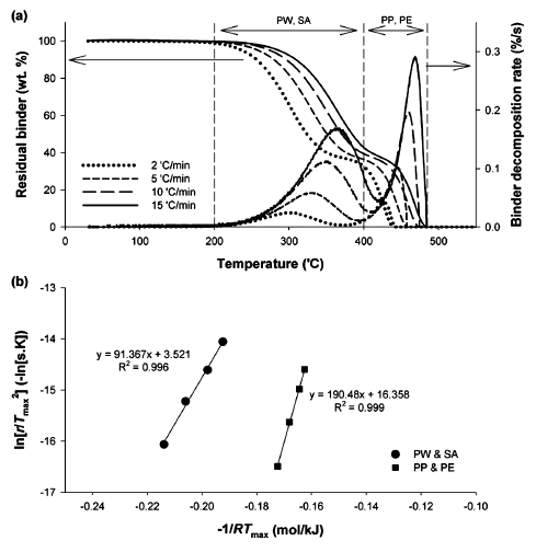
Thermal decomposition behavior of nano feedstock: (a) decomposition behavior and (b) calculation of decomposition activation energy.

Table 2
Sintered density and shrinkage at different sintering temperatures
| Temperature (°C) | 600 | 700 | 800 | 900 | 1000 |
|---|---|---|---|---|---|
|
|
|||||
| Density (g/cm3) | 5.01 | 5.74 | 6.36 | 6.86 | 6.84 |
| Shrinkage (%) | 10.39 | 14.39 | 17.23 | 19.31 | 19.24 |
Table 3
Sintered density and shrinkage at 900°C with different holding times
| Holding time (hour) | 0 | 1 | 2 | 3 |
|---|---|---|---|---|
|
|
||||
| Density (g/cm3) | 6.86 | 7.15 | 7.26 | 7.26 |
| Shrinkage (%) | 19.31 | 20.40 | 20.81 | 20.81 |
- Powder injection molding process for Fe nano powder was developed and optimized in this study. 100 nm powder and a wax-based binder system were used to formulate the feedstock. The critical solids loading of the powder was measured with torque rheometer as 45 vol. %. In order to provide process flexibility, the optimal solids loading was determined as 44 vol. %. Solvent debinding was conducted before thermal debinding to minimize defects. Unlike micro feedstock, paraffin wax and stearic acid in nano feedstock were not fully dissolved due to strong capillary force, and longer process time was required. Thermal decomposition behavior of the feedstock was analyzed by TGA. From the result, decomposition activation energies were calculated as 91.4 and 190.5 kJ/ mol for paraffin wax & stearic acid and polypropylene & polyethylene, respectively. Thermal debinding condition was also optimized with holding temperatures at 250 and 450°C. The optimal sintering cycle was determined depending on the density and hardness. The density increased up to 900°C, but it decreased at 1000°C due to phase transformation. Holding time effect was investigated as well, and the maximum hardness was obtained with 2 hours holding. As a result, the optimal sintering condition for nano feedstock was determined as 2 hours holding at 900°C, and near-full density samples were fabricated.
Conclusion
-
Acknowledgements
- We would like to acknowledge the financial support from the R&D Convergence Program of MSIP (Ministry of Science, ICT and Future Planning) and NST (National Research Council of Science and Technology) of Republic of Korea (Grant B551179-12-02-00). This work was supported by the National Research Foundation of Korea (NRF) grant funded by the Korea government (MSIP) (No. 2011-0030075).
Acknowledgement
- 1. R.M. German and A. Bose, Injection Molding of Metals and Ceramics, (1997) Metal Powder Industries Federation.
- 2. G. Wen, P. Cao, B. Gabbitas, D. Zhang and N. Edmonds: Metall. Mater. Trans., A Phys. Metall. Mater. Sci., (2013) 44 1530.ArticlePDF
- 3. U.M. Attia and J.R. Alcock: J. Micromech. Microeng., (2011) 21 043001.Article
- 4. J. Rajabi, N. Muhamad and A.B. Sulong: Microsyst. Technol., (2012) 18 1941.ArticlePDF
- 5. J.W. Oh, R. Bollina, W.S. Lee and S.J. Park: Powder Technol., (2016) 302 168.Article
- 6. P.C. Yu, Q.F. Li, J.Y. Fuh and P.W. Ho: Microsyst. Technol., (2009) 15 401.ArticlePDF
- 7. D. Lin, J. Lee and S.J. Park: J. Korean Powder Metall. Inst., (2016) 23 26.Article
- 8. J.W. Oh, W.S. Lee and S.J. Park: Powder Technol., (2017) 311 18.Article
- 9. A. Páez-Pavón, A. Jiménez-Morales, T.G. Santos, L. Quintino and J.M. Torralba: J. Magn. Magn. Mater., (2016) 416 342.
- 10. M.H. Ibrahim, N. Muhamad and A.B. Sulong: IJMME., (2009) 4 1.
- 11. H.E. Kissinger: Anal. Chem., (1957) 29 1702.Article
Figure & Data
References
Citations
Citations to this article as recorded by 

- Investigation of stainless steel 316L/zirconia joint part fabricated by powder injection molding
Chang Woo Gal, Sang Soo Han, Jun Sae Han, Dongguo Lin, Seong Jin Park
International Journal of Applied Ceramic Technology.2019; 16(1): 315. CrossRef - Fabrication and properties of Si3N4 based ceramics using combustion synthesized powders
Chang Woo Gal, Gi Woung Song, Woon Hyung Baek, Hyung Kyu Kim, Dae Keun Lee, Ki Wook Lim, Seong Jin Park
International Journal of Refractory Metals and Hard Materials.2019; 81: 325. CrossRef - Powder Injection Molding Process in Industrial Fields
Joo Won OH, Chang Woo GAL, Daseul SHIN, Jae Man PARK, Woo Seok YANG, Seong Jin PARK
Journal of the Japan Society of Powder and Powder Metallurgy.2018; 65(9): 539. CrossRef
Optimization of Process Condition for Fe Nano Powder Injection Molding


Fig. 1
Powder morphology of Fe nano powder.
Fig. 2
XRD pattern of Fe nano powder.
Fig. 3
Mixing torque of nano feedstock in different solids loading conditions: (a) mixing torque and (b) average value of stabilized mixing torque.
Fig. 4
Weight ratio of dissolved paraffin wax and stearic acid during solvent debinding.
Fig. 5
Thermal decomposition behavior of nano feedstock: (a) decomposition behavior and (b) calculation of decomposition activation energy.
Fig. 6
Dilatometric sintering data with sintering temperature of 1000°C.
Fig. 7
Microstructure of the sintered samples with different holding times: (a) without holding, (b) 1 hour, (c) 2 hours and (d) 3 hours.
Fig. 1
Fig. 2
Fig. 3
Fig. 4
Fig. 5
Fig. 6
Fig. 7
Optimization of Process Condition for Fe Nano Powder Injection Molding
| Mean particle size | Apparent density | Tap density | Pycnometer density |
|---|---|---|---|
|
|
|||
| 100 nm | 1.44 g/cm3 | 2.25 g/cm3 | 7.42 g/cm3 |
| Temperature (°C) | 600 | 700 | 800 | 900 | 1000 |
|---|---|---|---|---|---|
|
|
|||||
| Density (g/cm3) | 5.01 | 5.74 | 6.36 | 6.86 | 6.84 |
| Shrinkage (%) | 10.39 | 14.39 | 17.23 | 19.31 | 19.24 |
| Holding time (hour) | 0 | 1 | 2 | 3 |
|---|---|---|---|---|
|
|
||||
| Density (g/cm3) | 6.86 | 7.15 | 7.26 | 7.26 |
| Shrinkage (%) | 19.31 | 20.40 | 20.81 | 20.81 |
| Holding time (hour) | Vickers hardness (Hv) | Grain size (μm) | ||
|---|---|---|---|---|
|
|
||||
| Average | Standard deviation | Average | Standard deviation | |
|
|
||||
| 0 | 75.02 | 1.93 | 1.92 | 0.80 |
| 1 | 81.56 | 2.59 | 2.45 | 0.65 |
| 2 | 81.94 | 2.35 | 3.17 | 1.35 |
| 3 | 76.06 | 2.69 | 3.89 | 1.65 |
Table 1
Characteristic of Fe nano powder
Table 2
Sintered density and shrinkage at different sintering temperatures
Table 3
Sintered density and shrinkage at 900°C with different holding times
Table 4
Holding time dependency of Vickers hardness and grain size
Table 1
Table 2
Table 3
Table 4
TOP
 KPMI
KPMI

 Cite this Article


