Articles
- Page Path
- HOME > J Powder Mater > Volume 30(1); 2023 > Article
-
Article
- Fabrication of Equiatomic CoCrFeMnNi High-Entropy Alloy by Metal Injection Molding Process Using Coarse-Sized Powders
- Eun Seong Kima, Jae Man Parkb, Ji Sun Leea, Jungho Choea,c, Soung Yeoul Ahna, Sang Guk Jeonga, Do Won Leea, Seong Jin Parkb, Hyoung Seop Kima,d,*
-
Journal of Korean Powder Metallurgy Institute 2023;30(1):1-6.
DOI: https://doi.org/10.4150/KPMI.2023.30.1.1
Published online: January 31, 2023
a Department of Materials Science and Engineering, Pohang University of Science and Technology (POSTECH), Pohang 37673, Republic of Korea
b Department of Mechanical Engineering, Pohang University of Science and Technology (POSTECH), 77 Cheongam-Ro, Nam-Gu, Pohang, Gyeongbuk 37673, Republic of Korea
c Department for 3D Printing Materials, Korea Institute of Materials Science, Changwon 51508, Republic of Korea
d Graduate Institute of Ferrous Technology, Pohang University of Science and Technology (POSTECH), Pohang 37673, Republic of Korea
- * Corresponding Author: Hyoung Seop Kim, TEL: +82-54-279-2150, FAX: +82-54-279-2399, E-mail: hskim@postech.ac.kr
- - E. S. Kim·J. M. Park·J. S. Lee·J. Choe·S. Y. Ahn· S. G. Jeong·D. W. Lee: 학생, S. J. Park·H. S. Kim: 교수
© The Korean Powder Metallurgy Institute. All rights reserved.
- 1,545 Views
- 33 Download
- 3 Crossref
Abstract
- High-entropy alloys (HEAs) are attracting attention because of their excellent properties and functions; however, they are relatively expensive compared with commercial alloys. Therefore, various efforts have been made to reduce the cost of raw materials. In this study, MIM is attempted using coarse equiatomic CoCrFeMnNi HEA powders. The mixing ratio (powder:binder) for HEA feedstock preparation is explored using torque rheometer. The block-shaped green parts are fabricated through a metal injection molding process using feedstock. The thermal debinding conditions are explored by thermogravimetric analysis, and solvent and thermal debinding are performed. It is densified under various sintering conditions considering the melting point of the HEA. The final product, which contains a small amount of non-FCC phase, is manufactured at a sintering temperature of 1250°C.
- High entropy alloys (HEAs) have altered the concept of conventional alloy design [1]. Five or more main elements are combined to form a single-phase structure with maximized configuration entropy, and due to this feature, excellent properties such as strength, corrosion resistance, wear resistance, radiation resistance, and weldability have been reported in various HEA. Among the various HEA alloys, the most extensively studied equivalent CoCrFeMnNi is an alloy with a stable FCC singlephase structure above 800°C [2, 3]. It has been reported to have better resistance to hydrogen embrittlement than stainless steel [4], and has been reported to have excellent tensile strength and fracture toughness at low temperatures, making it a candidate material attracting attention in the hydrogen economy [5]. However, because HEA is quite expensive compared to cheap Fe base and Al base alloys, it is necessary to inspect more closely for application to parts [6]. Various processes such as casting [7], spark plasma sintering [8], direct energy deposition [9], powder bed fusion [10], binder jet [11], Metal Injection molding [12] have been performed for the manufacturing method of HEA. Among them, the powder metallurgy process has the advantage of being cheaper to manufacture parts compared to other processes, therefore it can overcome the burden of HEA's high material price [13].
- Metal Injection Molding (MIM) is a process in which accurate plastic injection molding techniques are applied to powder metallurgy technology [14]. First, it is injected into a mold considering the part shape using a feedstock mixed with powder and binder. Next, the debinding process removes the binder and sintering can produce final products with considerable density. Also, this process has the advantage of being able to manufacture complex three-dimensional parts in net shapes without post-processing (machining), in the way of producting shapes by machining high-entropy alloys at high prices [15]. In other words, it is an environmentally friendly process with no wasted materials, and costs are reduced. In addition, this process has the advantage of excellent productivity as it is no different from plastic injection molding. However, there are also disadvantages that need to be solved. A debinding process takes a lot of time, and it is essential to understand the entire process to achieve deformation and numerical accuracy of parts during sintering [12, 14, 15]. In addition, the price and collect rate are different depending on the size of the powder when manufacturing the powder using atomizing process, and the size of the powder used in the MIM process is usually fine (up to ~25 μm), so the price is relatively expensive compared to the size used in other powder metallurgy [14].
- In this study, cost was saved by manufacturing netshaped parts without material waste, and cheaper coarsesized powder (45~150 μm) was used. Through this study, it was investigated whether the MIM process can be used to lower the cost barrier for HEA use and whether the MIM process can be successfully manufactured even with coarse-sized powders.
1. Introduction
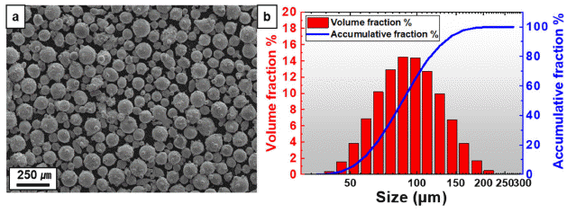
- CoCrFeMnNi high-entropy alloy was adopted for MIM process. The powders were produced by gas atomization (MK Inc., Ar atmosphere). To investigate the sphericity of the powder, a field emission scanning electron microscope (SEM, XL-30S FEG, FEI Co., 5 kV) was used (Fig. 1a). A laser particle size analyzer (Mastersizer 3000, Malvern) was used to analyze the size and distribution of the powder (Fig. 1b). In addition, inductively coupled plasma atomic emission spectroscopy (ICP-OES, LEEMAN) was performed to analyze the composition of the powder (Table 1).
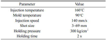
- To prepare the feedstock to be used in the MIM process, a wax-based binder system made of paraffin wax (PW), stearic acid (SA), polypropylene (PP) and polyethylene (PE) was chosen (Table 2). A torque rheometer (Rheomix QC Lab Mixer, HAAKE, 145°C, 150 rpm) was used to explore the powder to binder ratio of the feedstock. The MIM (TR30EH, Sodick) process was performed on a cuboid mold (length: 65 mm, width: 20 mm, height: 7 mm) (Table 3). A thermogravimetric analyzer (TGA, TGA/DSC 1, Mettler Toledo) was used to find the debinding conditions of the fabricated green parts. Solvent debinding was performed using n-Hexane at 45°C, and thermal debinding was performed in a furnace (1600G Tube furnace, Abrostate Overseas). The fabricated brown parts were sealed with a vacuum glass tube to avoid oxidation and sintering was performed.
- For the microstructure analysis of the sintered parts, optical microscope (OM, BX51M, Olympus) was performed mechanical polishing from #400 to #1200 using SiC paper, 3 μm and 1 μm using diamond suspension. In addition, electron backscatter diffraction (EBSD, XL30S, Philips, 20 kV, step size = 1.5 μm) was used after mechanical- chemical polishing using colloidal silica suspension. For EBSD results, orientation imaging microscope analysis (OIM Analysis 7, TSL) was used.
2. Experimental
CoCrFeMnNi high-entropy alloy powders: (a) SEM micrograph, (b) particle size distributions. Considering the accumulative fraction of these distributions, D10 = 56.0 μm, D50 = 86.2 μm, D90 = 133 μm, respectively. In contrast to the typical powders for MIM processing, coarser sized powders were prepared.

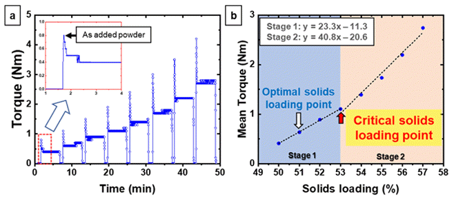
- A torque rheometer was used to determine the optimal feedstock ratio (powder:binder) for the MIM process. In Fig. 2a, the powder was gradually added by 1 vol. % from powder 46 vol. % and the torque was measured for 5 minutes. The torque temporarily increased whenever powder was added, and soon it converged to a constant torque as it started to mix with the binder.
- Figure 2b shows the average torque measured for each section from the torque rheometer profile (Fig. 2a) considering the powder ratio. The trend line was fitted by dividing the stage based on the point where the torque suddenly changes. Stage 1 was an excess binder stage, and the ratio of binder was still higher, so there was slightly increase in torque. As the powder ratio increased from Stage 2, the torque significantly increased. The solid 53 vol. % point was estimated as the critical solids loading point (red arrow). However, higher powder ratio than the critical solids loading can cause the difficulty of molding due to the existence of void in feedstock. Commonly, the feedstock balance, which is about 2~5 vol. % lower than the critical solid loading point, is adopted as the optimal solids loading point (white arrow), and as a result, the MIM process was carried out by producing solid 51 vol. % (powders:binder = 51:49) feedstock (Table 3).
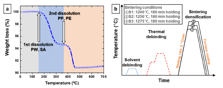
- To remove the binder in the green parts, solvent debinding process was performed (45°C, 12 h, solvent: n-Hexane), and most of PW and SA were decomposed through this procedure. Thermogravimetric changes were recorded using TGA to thermally decompose the remaining small amounts of PW, SA with the binders PP and PE (Fig. 3a). The decomposition of PW and SA was analyzed in the first sigmoid curve section, and the decomposition of PP and PE was analyzed in the second sigmoid curve section. Considering these results, the thermal debinding process conditions of the two steps were determined (2 step, 3 h, atmosphere: Ar). In step 1, remained PW and SA were decomposed at 200°C. In step 2, PP and PE were decomposed at 400°C with a slow heating rate (2°C/min) to avoid shape distortion (Fig. 3b). In addition, CoCrFeMnNi HEA is a FCC phase that is stable above 800°C, and its melting point has been reported ~1300°C [12]. Therefore, three sintering conditions (S1: 1200°C, S2: 1250°C, S3: 1275°C) were selected at a temperature below 1300°C to manufacture FCC single-phase CoCrFeMnNi HEA sintered parts (Fig. 3b).
- Figure 4 is the OM micrographs with porosity. Porosity values were calculated using 2D image analysis with low-magnification OM images. At S1, which is the lowest temperature among the three sintering conditions, it was observed that necking was formed between the powders, but sintering did not occur beyond that (Fig. 4a). It shows the opening porous shape while almost maintaining the powder shape. S1 is unsuitable for sintering process conditions. In S2, sintering progressed significantly, and it was observed that large or small pores were irregularly present (Fig. 4b). Some of the pores observed in S2 can be assumed to be the remaining pores captured during powder manufacturing, and the other pores can be assumed to be closed pores formed by sintering. In S3, pores was mostly observed at the grain boundary (Fig. 4c). It is assumed that the pores inside the grain migrated to the grain boundary because moving pores proceeded under the highest temperature condition.
- Figure 5 is inverse pole figure (IPF) map, and IPF color expresses FCC and BCC textures. Textures were not prominently identified in all maps. This means that the HEA manufactured by MIM is not an anisotropic material, and as a result of estimating the grain size, the grain size average (GSavg) increased in the order of S2 and S3.
- In Fig. 6, kernel average misorientation (KAM) map was investigated to analyze the dislocation density-based strain distribution, and the KAM value tended to decrease as the sintering temperature increased. The highest KAM value was measured in S1 where sintering hardly progressed (Fig. 6a). In S2, a relatively high KAM value is observed mainly around pores. Because the pore is empty, it can accommodate the deformation during the cooling process, so it can be estimated that it is relatively higher than the matrix area (Fig. 6b). In S3, which has the lowest KAM value, as in S2, the KAM value was measured relatively higher than that of the matrix around a small amount of pores, and it was estimated to have a lower level of thermal deformation than S2 (Fig. 6c).
- In S3, the KAM value was low as in S2, and the KAM value was measured to be relatively higher than that of the matrix along with a small amount of pores, and it is assumed that the porosity accepted the thermal strain similarly to S2 (Fig. 6c).
- Figure 7 is the phase map. In all sintered parts, a small amount of sigma phase and BCC phase were observed instead of FCC single phase. It has been reported that CoCrFeMnNi HEA has phases such as sigma and B2 phases identified below 800°C [2]. However, it is reported that during the sintering process, a BCC phase may be formed rather than the commonly reported B2 phase due to higher Cr at the grain boundary with the segregated compositions [12]. The highest FCC fraction in S2 and the densest sintered parts in S3 were successfully fabricated.
- In addition, CoCrFeMnNi HEA is an FCC-based HEA in which twinning is activated by annealing or deformation due to its low SFE, and the twin boundary (Ʃ3) induced by annealing twin is formed in the process of slowly cooling [16]. Furthermore, in S1, an annealing twin occurred (twin boundary fraction: 67.0%), which was not present in the powder, and unlike when rapidly cooled by atomizing, it was an annealing twin induced during slow cooling from a high temperature to room temperature (Fig. 7a). Both S2 and S3 are occured some annealed twin (twin boundary fraction: 27.7%, 24.6%), which can be induced under slow cooling sintering conditions. (Fig 7b, c). There was a difference between phase fraction and annealing twin fraction between S2 and S3. Through the overall results, additional analyzes (EDS, XRD, etc.) are required to determine whether the difference between the phase fraction and the twin fraction occurs due to the influence of sintering conditions or the composition is changed during sintering.
3. Result & discussion
(a) Torque rheometer profile. Red squares are partially enlarged. The powders were gradually added to the mixture of powder and binder in consideration of vol. %. (b) Average torque and its trend line considering the powder and binder ratio.

(a) TGA results of weight loss in feedstock with increasing temperature, (b) schematic of debinding and sintering.

EBSD-KAM map: (a) S1, (b) S2, (c) S3. Maximum orientation 5° with 3rd nearest neighbor kernel.

EBSD-Phase map with annealing twin: (a) S1, (b) S2, (c) S3. Yellow color lines are twin boundary (Ʃ3). Grain boundary color is black and twin boundary color is yellow.

- In the current study, CoCrFeMnNi HEA was fabricated by the MIM process using relatively coarser-sized powders than those previously used in the MIM process. After using TGA to determine the temperature at which the binder thermally dissolves, the manufactured green parts were performed to debinding. In consideration of the melting point, the debound parts were sintered under three different conditions. At 1200°C, sintering hardly progressed; at 1250°C, sintering occurred but a lot of pores remained inside the grain; it was sintered more densely at 1275°C, but the pores became larger and were moved to the region where the grain boundary overlapped. According to the MIM process study, considerable sintered parts could be fabricated even with coarsesized powders, furthermore, more optimized process conditions need to be found to fabricate dense sintered parts.
4. Conclusion
-
Acknowledgements
- This work was supported by the National Research Foundation (NRF) of the Republic of Korea (2021R1A 2C3006662 and 2022R1A5A1030054). Eun Seong Kim is also supported by Basic Science Research Program through the National Research Foundation of Korea (NRF) funded by the Ministry of Education (2022R1A 6A3A13073830).
Acknowledgments
- 1. D. B. Miracle: Nat. Commun., 10 (2019) 1805..ArticlePubMedPMC
- 2. R. B. Mane, Y. Rajkumar and B. B. Panigrah: Powder Metallurgy, 61 (2018) 131..Article
- 3. F. Otto, A. Dlouhý, K. G. Pradeep, M. Kuběnová, D. Raabe, G. Eggeler and E. P. George: Acta Mater., 112 (2016) 40..Article
- 4. H. Luo, Z. Li, W. Lu, D. Ponge and D. Raabe: Corros. Sci., 136 (2018) 403..Article
- 5. B. Gludovatz, A. Hohenwarter, D. Catoor, E. H. Chang, E. P. George and R. O. Ritchie: Science, 345 (2014) 1153..ArticlePubMed
- 6. J. Moon, J. M. Park, J. W. Bae, H.-S. Do, B.-J. Lee and H. S. Kim: Acta Mater., 193 (2020) 71..Article
- 7. J. H. Kim, K. R. Lim, J. W. Won, Y. S. Na and H.-S. Kim: Mater. Sci. Eng. A, 712 (2018) 108..Article
- 8. S. H. Joo, H. Kato, M. J. Jang, J. Moon, E. B. Kim, S. J. Hong and H. S. Kim: J. Alloys Compd., 698 (2017) 591..Article
- 9. R. Savinov, Y. Wang, J. Wang and J. Shi: Procedia Manuf., 53 (2021) 435..Article
- 10. J. M. Park, J. Choe, J. G. Kim, J. W. Bae, J. Moon, S. Yang, K. T. Kim, J.-H. Yu and H. S. Kim: Mater. Res. Lett., 8 (2020) 1..Article
- 11. Z. Xu, Z. Zhu, P. Wang, G. K. Meenashisundaram, S. M. L. Nai and J. Wei: Addit. Manuf., 35 (2020) 101441..Article
- 12. Y. Zhang, T. Bian, X. Shen, Z. Wang, S. Ye, S. Feng, K. Yu, C. Ding and P. Yu: J. Alloys Compd., 868 (2021) 158711..Article
- 13. A. Araoyinbo, F. Ishola, E. Salawu, M. Biodun and A. Samuel: Overview of powder metallurgy process and its advantages, AIP Conference Proceedings, AIP Publishing LLC, (2022) 020153..Article
- 14. D. F. Heaney: Handbook of metal injection molding, Woodhead Publishing (2018)..
- 15. S. V. Atre, T. J. Weaver and R. M. German: Injection Molding of Metals and Ceramics, SAE Technical Paper, 1998..
- 16. P. P. Bhattacharjee, G. D. Sathiaraj, M. Zaid, J. R. Gatti, C. Lee, C.-W. Tsai and J.-W. Yeh: J. Alloys Compd., 587 (2014) 544..Article
Figure & Data
References
Citations

- Development of 3D interconnected nanoporous TiZrHfNbTaNi high-entropy alloy via liquid metal dealloying and subsequent synthesis of (TiZrHfNbTaNi)O high-entropy oxide
Jae Hyuk Lee, Soo Vin Ha, Jihye Seong, Akira Takeuchi, Ruirui Song, Hidemi Kato, Soo-Hyun Joo
Journal of Materials Research and Technology.2025; 35: 5204. CrossRef - Development of 3D interconnected heterogeneous high-entropy alloy composites with enhanced multifunctionality via liquid metal dealloying
Munsu Choi, Gang Hee Gu, Jongun Moon, Jae Wung Bae, Hidemi Kato, Seung Zeon Han, Hyoung Seop Kim, Yongseok Choi, Soo-Hyun Joo
Journal of Materials Research and Technology.2025; 37: 5672. CrossRef - Characterization of the Manufacturing Process and Mechanical Properties of CoCrFeMnNi High-Entropy Alloys via Metal Injection Molding and Hot Isostatic Pressing
Eun Seong Kim, Jae Man Park, Do Won Lee, Hyojeong Ha, Jungho Choe, Jaemin Wang, Seong Jin Park, Byeong-Joo Lee, Hyoung Seop Kim
journal of Korean Powder Metallurgy Institute.2024; 31(3): 243. CrossRef


Fig. 1
Fig. 2
Fig. 3
Fig. 4
Fig. 5
Fig. 6
Fig. 7
Table 1
Table 2
Table 3
TOP
 KPMI
KPMI


 Cite this Article


