
Articles
- Page Path
- HOME > J Powder Mater > Volume 31(1); 2024 > Article
-
General Article
- Cryogenic Tensile Behavior of Ferrous Medium-entropy Alloy Additively Manufactured by Laser Powder Bed Fusion
- Seungyeon Leea,b, Kyung Tae Kima, Ji-Hun Yua, Hyoung Seop Kimc,d,e, Jae Wung Baeb,*, Jeong Min Parka,*
-
Journal of Powder Materials 2024;31(1):8-15.
DOI: https://doi.org/10.4150/KPMI.2024.31.1.8
Published online: February 28, 2024
aDepartment of 3D Printing Materials, Korea Institute of Materials Science (KIMS), Changwon 51508, Republic of Korea
bDepartment of Metallurgical Engineering, Pukyong National University, Busan 48513, Republic of Korea
cDepartment of Materials Science and Engineering, Pohang University of Science and Technology (POSTECH), Pohang 37673, Republic of Korea
dGraduate Institute of Ferrous and Energy Materials Technology (GIFT), Pohang University of Science and Technology (POSTECH), Pohang 37673, Republic of Korea
eCenter for Heterogenic Metal Additive Manufacturing, Pohang University of Science and Technology (POSTECH), Pohang 37673, Republic of Korea
-
*Corresponding Author: Jae Wung Bae, TEL: +82-51-629-6346, E-mail: jwbae@pknu.ac.kr
*Jeong Min Park, TEL: +82-55-280-3502, E-mail: jmpark@kims.re.kr - - S. Lee: 연구원, K. T. Kim, J. H. Yu: 책임연구원, H. S. Kim, J. W. Bae: 교수, J. M. Park: 선임연구원
© 2024 The Korean Powder Metallurgy & Materials Institute
This is an Open Access article distributed under the terms of the Creative Commons Attribution Non-Commercial License (http://creativecommons.org/licenses/by-nc/4.0/) which permits unrestricted non-commercial use, distribution, and reproduction in any medium, provided the original work is properly cited.
- 5,800 Views
- 147 Download
- 6 Crossref
Abstract
- The emergence of ferrous-medium entropy alloys (FeMEAs) with excellent tensile properties represents a potential direction for designing alloys based on metastable engineering. In this study, an FeMEA is successfully fabricated using laser powder bed fusion (LPBF), a metal additive manufacturing technology. Tensile tests are conducted on the LPBF-processed FeMEA at room temperature and cryogenic temperatures (77 K). At 77 K, the LPBF-processed FeMEA exhibits high yield strength and excellent ultimate tensile strength through active deformation-induced martensitic transformation. Furthermore, due to the low stability of the face-centered cubic (FCC) phase of the LPBF-processed FeMEA based on nano-scale solute heterogeneity, stress-induced martensitic transformation occurs, accompanied by the appearance of a yield point phenomenon during cryogenic tensile deformation. This study elucidates the origin of the yield point phenomenon and deformation behavior of the FeMEA at 77 K.
- High-entropy alloys (HEAs) and medium-entropy alloys (MEAs), defined as the alloys having multiple principal elements with high configurational entropy (ΔSconf) as compared to that of conventional dilute materials, are attracting considerable attentions due to their excellent performance in extreme environments, including extremely low and high temperatures [1-6]. The concept of this type of alloys can be categorized based on the configuration entropy in to HEAs (1.5R ≤ ΔSconf, R = gas constant) and MEAs (1.0R ≤ ΔSconf ≤ 1.5R) [3, 4]. Particularly, because single face-centered cubic (FCC) structured alloys have been reported to exhibit excellent load-bearing capacity at cryogenic temperatures, this novel material expected to be used in aerospace, arctic offshore plant, cryogenic maritime, and hydrogen transport applications [7-10]. However, because single FCC-structured HEAs typically exhibit superfluous elongation, but low yield strength, numerous studies have been performed for alloy design for high strength FCC-structured alloys based on severe lattice distortion or precipitation hardening [5, 11, 12]. Moreover, the recent studies intensively focused on applying novel process for enhancing yield strength of FCC-structure HEAs such as heterostructuring, severe plastic deformation, etc [13, 14].
- Recently, laser powder bed fusion (LPBF), which is the most the famous laser-based additive manufacturing technique, garners significant attention in various high-tech industries because of not only its high precision and great freedom of design for producing complex-shaped products not achievable through traditional processes [15-18]. Particularly, the recent studies proposed that applying LPBF can enhance the mechanical properties of the FCC-structured HEAs via producing hierarchically heterogeneous microstructure [19-23]. The various studies were performed for process-structure-property relationship of LPBFed HEAs to expand applicability of LPBF and develop high performance alloys [22-27].
- Meanwhile, among the various alloys reported thus far, ferrous medium-entropy alloys (FeMEAs), are known to exhibit superior tensile properties at cryogenic temperature due to lower FCC phase stability promoting a deformation-induced martensitic transformation as Fe content rises [28-30]. Furthermore, recent studies have indicated that when the LPBF process is applied to the alloy, transformation-induced plasticity (TRIP) can be stimulated by compositional heterogeneity around cell structure, a unique microstructure of LPBFed materials [31]. On the other hands, while the FeMEA exhibits attractive mechanical performance at cryogenic temperature, the study of cryogenic tensilbe behavior of LPBFed FeMEA has not been performed. In this study, the FeMEA with a nominal composition of Fe60Co15Ni15Cr10 (at%) was successfully printed by LPBF, and the printed sample exhibit exceptional tensile properties at liquid nitrogen atomosphere. The cryogenic deformation behavior of LPBFed FeMEA was explored with microstructure analysis in various scale.
1. Introduction
- 2.1. Sample fabrication
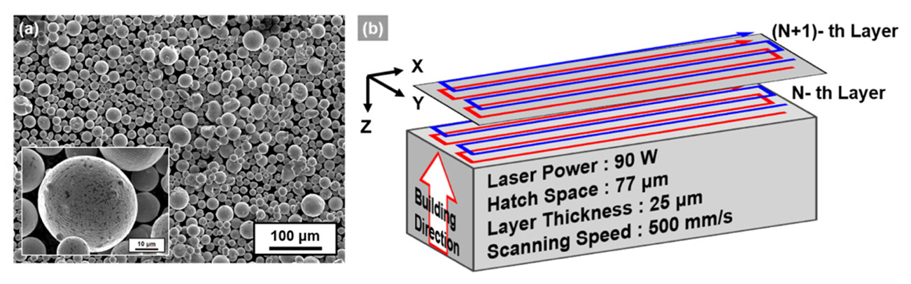
- As the raw materials, spherical powder of Fe60Co15Ni15Cr10 (at%) alloy with a particle size distribution ranging from 10–55 μm was prepared using the gas atomization process, as shown in Fig. 1(a). B using a commercial LPBF machine (Mlab, Concept Laser GmbH, Germany), rectangular-shaped samples (30 × 6 × 6 mm) were printed under a laser power of 90W, a hatch spacing of 77 μm, and a layer thickness of 25 μm in an Ar atmosphere. The laser scanning was performed in a meander scan pattern with 180° rotation in every layers, as schematically described in Fig. 1(b). Note that the scanning direction denoted as X-axis, the direction perpendicular to scanning direction and building direction as the Y-axis, and the building direction as the Z-axis. Moreover, to fabricate the samples without macroscopic defects, the heat input was controlled by controlling the scanning speed. As depicted in the schematic in Fig. 1(b), double-laser scanning was performed at a scanning speed of 500 mm/s for not only sufficient melting of the powder but also minimizing element evaporation due to excessive heat input [31]. Table 1 presents the chemical composition of the powder and LPBFed sample, which measured by using energy-dispersive X-ray spectroscopy (EDS), a C/S analyzer (CS-800, ELTRA GmbH, Germany), and an O/N analyzer (ONH-836, LECO Co., USA). As shown in Table 1, the elemental composition of substitutional elements of the powder was not tilted by LPBF, but the oxygen concentration of the sample increased after LPBF process.
- 2.2. Microstructure analysis and cryogenic tensile test
- For the microstructure analysis of the samples, backscattered electron (BSE) analysis, electron backscatter diffraction (EBSD) analysis, and energy-dispersive X-ray spectroscopy (EDS) analysis, were performed in a fieldemission scanning electron microscope (FE-SEM, JSM-7800F PRIME, JEOL Ltd., Japan) system. All the specimens were polished up to SiC abrasive paper 1200 grit, followed by electrolytic polishing using an etchant solution of 8% HClO4 and 92% CH3COOH. Transmission electron microscope (TEM) analysis was also conducted to analyze the nano-sized structure in the LPBFed samples using a TEM instrument (JEM-2200FS JEOL Ltd., Japan). The sample for TEM analysis was produced by performing electrolytic polishing based jet polishing through a mixture of 10% HClO4 and 90% CH3COOH on a thin disk specimen polished to a thickness of 50 μm.
- To evaluate the tensile properties of the samples, dogbone-shaped tensile specimens (gauge length 5.0 mm × gauge width 2.5 mm × thickness 1.5 mm) were extracted from the rectangular samples with the X-direction as the tensile axis. Tensile tests were conducted using a universal testing machine (INSTRON 1361, Instron Corp., USA) equipped with a liquid-nitrogen chamber. For the tensile testing at cryogenic temperature, the specimens were tested at a strain rate of 10-3 s-1 while fully immersed in liquid nitrogen. To precisely measure the total elongation of the tensile specimens, markings were made at the gauge ends of each tensile specimen using a Vickers hardness tester. The actual length of the tensile-fractured specimens was measured to correct the total elongation. To ensure the reliability of the tensile data, all the tensile tests were repeated a minimum of three times.
2. Experimental
- 3.1. Initial microstructure
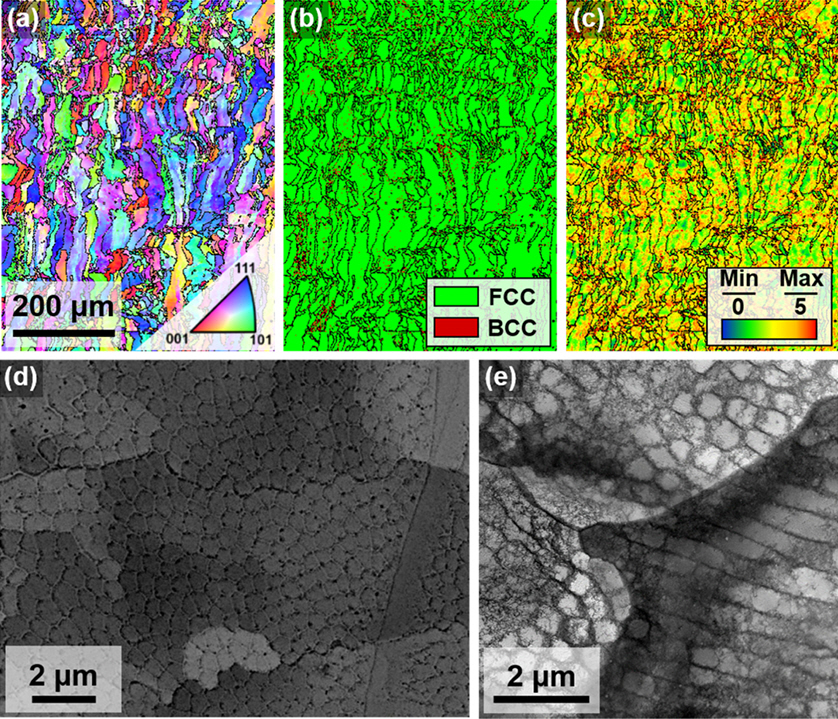
- Fig. 2 presents the microstructure of the FeMEA printed by LPBF. As shown in EBSD inverse pole figure (IPF) map (Fig. 2(a)), the grains are mostly elongated along the build direction (Z direction). The EBSD phase map (Fig. 2(b)) confirms that the LPBFed FeMEA consists of a nearly single FCC phase, where the fraction of the BCC phase is less than 1%. During the LPBF, the repetitive heating and cooling cycles with high cooling temperature usually result in high residual dislocation density in the processed materials. As indicated in EBSD KAM map (Fig. 2 (c)), the LPBFed samples exhibited high levels of dislocation density, corresponding to the high kernel average misorientation (KAM) values distribution. Furthermore, a number of dislocations are distributed along the boundaries of the cell structure during the LPBF process, as presented in the SEM-BSE image (Fig. 2(d)). Fig. 2(e) shows TEM micrographs of the cell structure, and it can be seen that a large number of dislocations are decorated at the cell boundary.
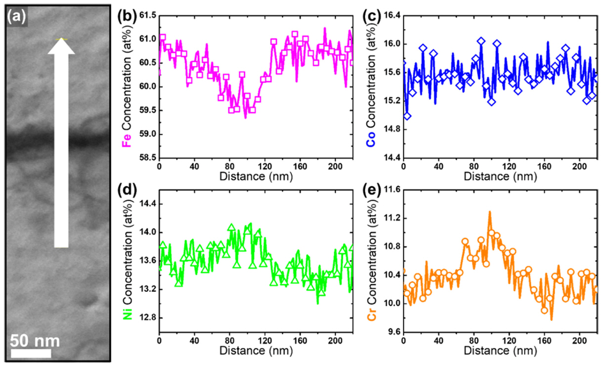
- On the other hand, it has been well-reported that the solute segregation is accompanied at these dislocation network in the LPBFed alloys, which is quite distinct from the deformation-induced cell structure observed in plastic-deformed alloys [32, 33]. Fig. 3 presents the TEM EDS line profile across the cell boundaries of the LPBFed FeMEAs, which indicates a sparse presence of Fe composition at the cell boundaries. In other words, the cell interiors have a higher Fe content compared to the cell boundary. This compositional difference leads to distinct FCC phase stability between the cell boundaries and interiors. Such characteristics are in stark contrast to those of fully-recrystallized FeMEAs having a uniform composition distribution [29, 34]. In our previous studies, the average Gibbs free energy to be converted from FCC to body-centered cubic (BCC) structure was calculated as - 4019 J/mol in the cell interiors, and this value is a phase stability value that can generate TRIP in an FeMEA during plastic deformation at room temperature [31].
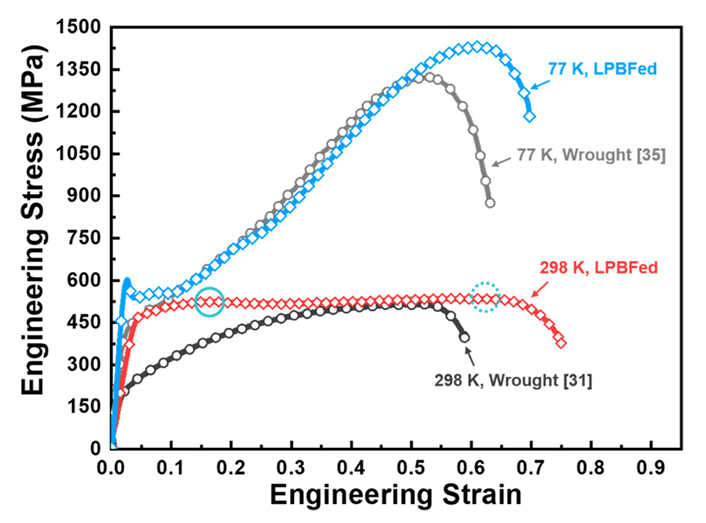
- Fig. 4 presents the engineering stress–strain curves at room temperature (298 K) and cryogenic temperature (77 K) for the LPBFed FeMEA and the wrought FeMEA (produced by casting + homogenization heat treatment + cold rolling + heat treatment at 800ºC for 1 h, referred to as CR+HT sample) [31, 35]. At cryogenic temperature, the elastic modulus is higher than that at room temperature, which was attributed to the temperature dependency of elastic modulus [36].
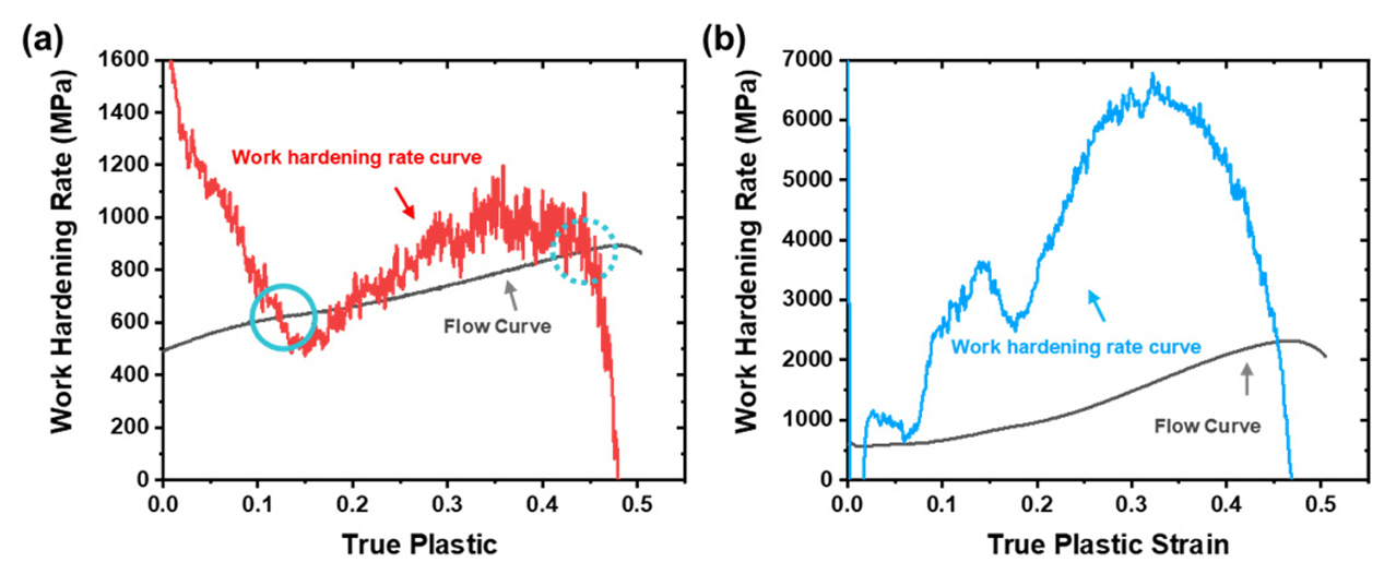
- At room temperature, the LPBFed sample exhibited a yield strength of ~460 MPa, more than twice as high as that of CR+HT samples with a homogeneous microstructure [31]. The notable difference can be attributed to the high dislocation density at the cell structure of the LPBFed sample structure [37]. Furthermore, solute segregation can stabilize the cell boundaries in the LPBFed samples, and cell boundaries effectively impede dislocation movement leading to enhanced strength [38-40]. Fig. 5(a) presents the work hardening rate and true stress as a function of true plastic strain for the tensile behaviors of the LPBFed sample at room temperature. Interestingly, in the post-elongation region after 1st necking point (marked by solid circle in Fig. 5(a)), the strain hardening rate is rapidly accelerated, promoting delaying plastic instability with significantly extended total elongation. This behavior is attributed to evolution of strain-induced martensite at the strain-localized region. As the strain-localized region gradually extends from the center to the gauge end, BCC martensitic transformation continuously propagates towards the gauge end, resulting in the significantly extended elongation to the 2nd necking point (represented by the dashed circle in Fig. 5(a)) [31, 41]. This phenomenon is attributed to low phase stability in cell interior of LPBFed FeMEA induced by solute heterogeneity around cell structure, and this tendency could not be observed in CR +HT sample with a homogeneous composition and microstructure.
- Meanwhile, the yield strength, ultimate tensile strength, and total elongation of the LPBFed FeMEA are measured to be 580 MPa, 1430 MPa, and 69%, respectively. Especially, as shown in Fig. 5(b), a steep increase in work hardening rate curve can be observed at the early stage of deformation at cryogenic temperature, which is similar to the trend observed in the cryogenic tensile behavior of wrought FeMEAs. This is attributed to a more pronounced BCC TRIP in the LPBFed FeMEA during plastic deformation at cryogenic temperatures compared to room temperature. The formation of BCC martensite during plastic deformation in FeMEAs is reported to effectively hinder the movement of dislocations. This, coupled with the active formation of geometrically necessary dislocations (GND) due to the strain gradient between the ductile FCC phase and the hard BCC phase, explosively increases the work hardening rate [30].
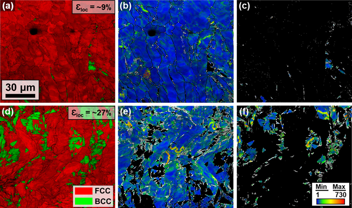
- Fig. 6 presents the deformed microstructure of the LPBFed alloy after tensile deformation at room temperature. As shown in Fig. 6(a), a small amount of deformation-induced martensite is observed in the deformation region before 1st necking. In the region at a local strain of 27% (Fig. 6(d)), the fraction of the martensitic significantly increases, which corresponding to an rapid increase in work hardening rate of the LPBFed FeMEA. Furthermore, as shown in Fig. 6(b, c, e, f), the GND density increases with an increase in strain, and this augmented GND density is particularly pronounced at the FCC/BCC interfaces.
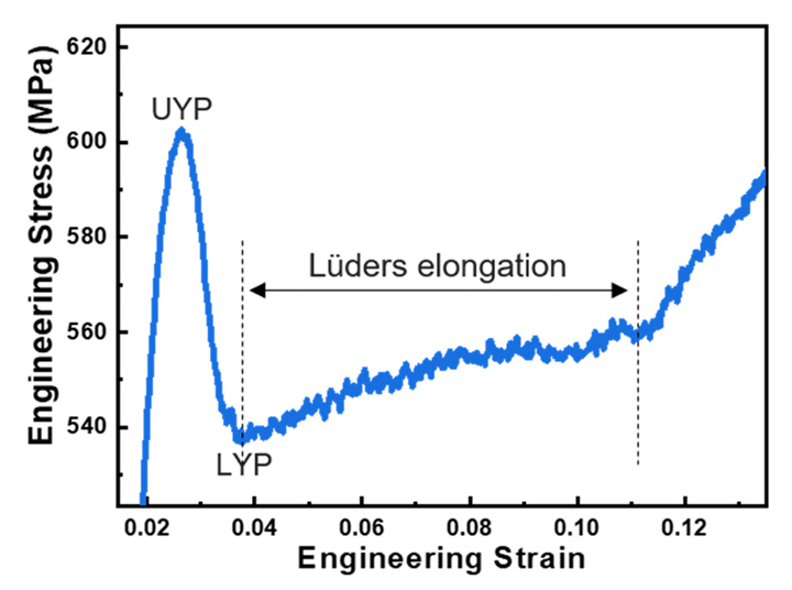
- Meanwhile, the LPBFed sample exhibited a yield point phenomenon (YPP) during cryogenic tensile deformation, unlike the CR+HT samples. Fig. 7 presents the region around the yield point in the cryogenic tensile curve of LPBFed FeMEAs. The upper yield point (UYP) was measured to be 600 MPa, whereas the lower yield point (LYP) was measured to be 540 MPa. The stress value at the UYP is significantly higher than that of the CR+HT sample [35].
- The YPP can be attributed to the stress-induced martensitic transformation in the LPBFed sample during cryogenic tensile deformation. Due to solute segregation at the cell boundary (Fig. 3), the LPBFed FeMEA exhibited lower FCC phase stability in the matrix compared to the CR + HT FeMEA having homogeneous microstructure. At the cryogenic temperatures, the ΔGFCC→BCC is significantly decreased as compared to that at room temperature. Therefore, since the deformation-induced martensitic transformation can be highly stimulated at cryogenic temperature, stress-induced martensite can be formed at a sufficient stress level in the elastic deformation region, leading to yielding of the LPBFed FeMEA at UYP. As the BCC phase has a larger volume than the FCC phase, this can lead decreasing engineering stress due to volume expansion. Furthermore, the martensitic transformation-based plastic deformation in the vicinity of the martensite, where numerous mobile dislocations are formed in the surrounding FCC phase, leads to a decrease in stress until the LYP [35, 41]. As shown in Fig. 4, a Lüders-type deformation occurs, which is similar to the cryogenic behavior of hot-rolled FeMEA. Lee et al. [35] investigated the cryogenic tensile behavior of hot-rolled FeMEAs, and the Lüders-type deformation with YPP was observed during cryogenic tensile deformation. They proposed that the stress-induced martensitic transformation generates mobile dislocations in neighboring FCC grains, and a rapid increase in mobile dislocation density causes a sudden decrease in the applied stress promoting YPP [35]. Gao et al. [41] also observed the Lüders-type deformation during tensile deformation of ultrafine-grained stainless steel. The Lüders band, formed in the deformation concentration region at the UYP, gradually spread to the surrounding area due to immediate martensitic transformation, leading to significantly extended elongation. For the LPBFed FeMEA, the stress-induced martensitic transformation leads the YPP, and gradual spreading the initiation of martensitic transformation can result in Lüders-type defor-mation. After Lüders-type deformation, the martensitic transformation is actively initiated on the gauge region of the tensile specimens, and the strain hardening rate is rapidly increased by profuse BCC TRIP promoting high ultimate tensile strength of the LPBFed FeMEA during cryogenic tensile deformation.
3. Results and Discussion
- In this study, the cryogenic tensile behavior of Fe60Co15Ni15Cr10 (at%) alloy printed by LPBF was investigated. The LPBFed FeMEA exhibited higher yield strength than those of CR + HT FeMEA having homogeneous microstructure, which is attributed to unique dislocation network in the LPBFed FeMEA. Furthermore, the LPBFed FeMEA exhibits steep strain hardening behavior with excellent tensile strength due to active evolution of BCC martensite due to low FCC stability as compared to the wrought FeMEA. Due to low FCC phase stability of the LPBFed FeMEA, stress-induced martensitic transformation occurred with YPP during the cryogenic tensile deformation. The martensitic transformation gradually spread to the gauge section of the tensile specimen, leading to Lüders-type deformation after LYP. After Lüders-type elongation, the overall gauge region of the tensile specimens is activated for martensitic transformation, and the strain hardening rate is rapidly increased by active BCC TRIP during tensile deformation of the LPBFed FeMEA at cryogenic temperature. This study can be expected to greatly contribute to widely expand the applications of the LPBFed FeMEA for extreme environments.
4. Conclusion
-
Acknowledgements
- This work was supported by the National Research Foundation of Korea (NRF) grant funded by the Ministry of Science and ICT of Korea (2021R1A2C3006662, 2022R1A5A1030054). This work was also supported by Principal R&D Project (PNK8960) of the Korean Institute of Materials Science (KIMS), and Basic Research Program (PICO960) of Korea Institute of Machinery and Materials (KIMM).


| Samples |
Chemical compositions, at% |
|||||||
|---|---|---|---|---|---|---|---|---|
| Fe | Co | Ni | Cr | C | S | O | N | |
| Powder | 60.06 | 16.47 | 12.79 | 10.47 | 0.05 | 0.02 | 0.11 | 0.04 |
| LPBFed | 60.20 | 15.41 | 14.10 | 9.71 | 0.14 | 0.02 | 0.39 | 0.04 |
- 1. D. B. Miracle: Nat. Commun., 10 (2019) 1805.
- 2. J. M. Park, D. C. Yang, H. Kim, D. G. Kim, S. Lee, H. S. Kim and S. S. Sohn: Mater. Res. Lett., 9 (2021) 315.Article
- 3. J. Moon, J. M. Park, J. W. Bae, H.-S. Do, B.-J. Lee and H. S. Kim: Acta Mater., 193 (2020) 71.Article
- 4. J. Moon, J. M. Park, J. W. Bae, N. Kang, J. Oh, H. Shin and H. S. Kim: Scr. Mater., 186 (2020) 24.Article
- 5. S. S. Sohn, A.K. Silva, Y. Ikeda, F. Kormann, W. Lu, W. S. Choi, B. Gault, D. Ponge, J. Neugebauer and D. Raabe: Adv. Mater., 31 (2019) 1807142.
- 6. O. Bouaziz, J. Moon, H. S. Kim and Y. Estrin: Scr. Mater., 191 (2021) 107.Article
- 7. B. Gludovatz, A. Hohenwarter, D. Catoor, E. H. Chang, E. P. George and R. O. Ritchie: Science., 345 (2014) 1153.Article
- 8. F.-R. Chen, D. V. Dyck and C. Kisielowski: Nat. Commun., 7 (2016) 10603.
- 9. S. H. Shim, J. Moon, H. Pouraliakbar, B. J. Lee, S. I. Hong and H. S. Kim: J. Alloys Compd., 897 (2022) 163217.Article
- 10. D. Liu, Q. Yu, S. Kabra, M. Jiang, P. F-Kreutzer, R. Zhang, M. Payne, F. Walsh, B. Gludovatz, M. Asta, A. M. Minor, E. P. George and R. O. Ritchie: Science., 378 (2022) 978.Article
- 11. Z. Li: Acta Mater., 164 (2019) 400.Article
- 12. Y.-J. Liang, L. Wang, Y. Wen, B. Cheng, Q. Wu, T. Cao, Q. Xiao, Y. Xue, G. Sha, Y. Wang, Y. Ren, X. Li, L. Wang, F. Wang and H. Cai: Nat. Commun., 9 (2018) 4063.
- 13. X. H. Du, W. P. Li, H. T. Chang, T. Yang, G. S. Duan, B. L. Wu, J. C. Huang, F. R. Chen, C. T. Liu, W. S. Chuang, Y. Lu, M. L. Sui and E. W. Huang: Nat. Commun., 11 (2020) 2390.
- 14. P. Sathiyamoorthi and H. S. Kim: Prog. Mater. Sci., 123 (2022) 100709.Article
- 15. T. Y. Kim, M. H. Kang, J. H. Kim, J. K. Hong, J. H. Yu and J. I. Lee: J. Powder Mater., 29 (2022) 99.Article
- 16. Y. Lee, E. S. Kim, S.-H. Chun, J. B. Seol, H. Sung, J. S. Oh, H. S. Kim, T. Lee, T.-H. Nam and J. G. Kim: J. Powder Mater., 28 (2021) 491.Article
- 17. H. Park, Y. W. Kim, S. Lee, K. T. Kim, J.-H. Yu, J. G. Kim and J. M. Park: J. Powder Mater., 30 (2023) 140.Article
- 18. Y. M. Wang, T. Voisin, J. T. McKeown, J. Ye, N. P. Calta, Z. Li, Z. Zeng, Y. Zhang, W. Chen, T. T. Roehling, R. T. Ott, M. K. Santala, P. J. Depond, M. J. Matthews, A. V. Hamza and T. Zhu: Nat. Mater., 17 (2018) 63.ArticlePDF
- 19. J. M. Park, E. S. Kim, H. Kwon, P. Sathiyamoorthi, K. T. Kim, J. H. Yu and H. S. Kim: Addit. Manuf., 47 (2021) 102283.Article
- 20. J. M. Park, J. Choe, J. G. Kim, J. W. Bae, J. Moon, S. Yang, K. T. Kim, J.-H. Yu and H. S. Kim: Mater. Res. Lett., 8 (2020) 1.ArticlePDF
- 21. Z. G. Zhu, X. H. An, W. J. Lu, Z. M. Li, F. L. Ng, X. Z. Liao, U. Ramamurty, S. M. L. Nai and J. Wei: Mater. Res. Lett., 7 (2019) 453.Article
- 22. Z. G. Zhu, Q. B. Nguyena, F. L. Nga, X. H. Anb, X. Z. Liao, P. K. Liaw, S. M. L. Nai and J. Wei: Scr. Mater., 154 (2018) 20.Article
- 23. J. M. Park: J. Powder Mater., 29 (2022) 132.Article
- 24. J. Ren, Y. Zhang, D. Zhao, Y. Chen, S. Guan, Y. Liu, L. Liu, S. Peng, F. Kong, J. D. Poplawsky, G. Gao, T. Voisin, K. An, Y. M. Wang, K. Y. Xie, T. Zhu and W. Chen: Nature., 608 (2022) 62.ArticlePDF
- 25. A. O. Moghaddam, N. A. Shaburova, M. N. Samodurova, A. Abdollahzadeh and E. A. Trofimov: J. Mater. Sci. Tech., 77 (2021) 131.
- 26. R. Li, P. Niu, T. Yuan, P. Cao, C. Chen and K. Zhou: J. Alloy. Compd., 746 (2018) 125.Article
- 27. A. Piglione, B. Dovgyy, C. Liu, C. M. Gourlay, P. A. Hooper and M. S. Pham: Mater. Lett., 224 (2018) 22.Article
- 28. J. W. Bae and H. S. Kim: Scr. Mater., 186 (2020) 169.Article
- 29. J. W. Bae, J. B. Seol, J. Moon, S. S. Sohn, M. J. Jang, H. Y. Um, B.-J. Lee and H. S. Kim: Acta Mater., 161 (2018) 388.Article
- 30. J. W. Bae, J. G. Kim, J. M. Park, W. Woo, S. Harjo and H. S. Kim: Scr. Mater., 165 (2019) 60.Article
- 31. J. M. Park, P. Asghari-Rad, A. Zargaran, J. W. Bae, J. Moon, J. Choe, S. Yang, J.-H. Yu and H. S. Kim: Acta Mater., 221 (2021) 117426.Article
- 32. J. M. Park, H. Kwon, J. Choe, K. T. Kim, J.-H. Yu, Y.-U. Heo and H. S. Kim: Scr. Mater., 237 (2023) 115715.Article
- 33. D. Kong, C. Dong, S. Wei, X. Ni, L. Zhang, R. Li, L. Wang, C. Man and X. Li: Addit. Manuf., 38 (2021) 101804.Article
- 34. J. Lee, S. Son, S. S. Sohn, J. W. Bae and H. S. Kim: Mater. Sci. Eng. A., 886 (2023) 145735.Article
- 35. J. Lee, H. Park, S. Son, J. W. Bae, J. Y. Kim, S. K. Kim, J. Jang and H. S. Kim: J. Mater. Sci. Tech., 177 (2024) 234.Article
- 36. G. Laplanche, P. Gadaud, O. Horst, F. Otto, G. Eggeler and E. P. George: J. Alloys Compd., 623 (2015) 348.Article
- 37. J. M. Park, J. Choe, H. K. Park, J. Jung, T. S. Kim, J.-H. Yu, J . G. Kim and H. S. Kim: Addit. Manuf., 35 (2020) 101333.Article
- 38. L. Liu, Q. Ding, Y. Zhong_, J. Zou, J. Wu, Y.-L. Chiu, J. Li, Z. Zhang, Q. Yu and Z. Shen: Mater. Tod., 21 (2018) 354.Article
- 39. D. Kong, C. Dong, S. Wei, X. Ni, L. Zhang, R. Li, L. Wang, C. Man and X. Li: Addit. Manuf., 38 (2021) 101804.Article
- 40. J. M. Park, H. Kwon, J. Choe, K. T. Kim, J.-H. Yu, Y.-U. Heo and H. S. Kim: Scr. Mater., 237 (2023) 115715.Article
- 41. S. Gao, Y. Bai, R. Zheng, Y. Tian, W. Mao, A. Shibata and N. Tsuji: Scr. Mater., 159 (2019) 28.Article
References
Figure & Data
References
Citations
- Stronger weld than base metal in face-centered cubic alloy through multi-scale heterogeneity
Yoona Lee, Sangwon Park, Dongwon Shin, Marcia Myung Hye Ahn, Wei Xiong, Nokeun Park, Hyoung Seop Kim, Je In Lee, Wookjin Lee, Yoon Suk Choi, Jeong Min Park, Namhyun Kang
Materials Research Letters.2026; 14(4): 386. CrossRef - Tensile behavior at cryogenic temperatures of Al 7075 + 1.8%wt Zr alloy processed by L-PBF
Gabrielle Tiphéne, Nicolas Nothomb, Marie-Noëlle Avettand-Fénoël, Aude Simar
Materials Science and Engineering: A.2026; 966: 150364. CrossRef - Effect of Building Orientation on Tensile Properties of Hastelloy X alloy Manufactured by Laser Powder Bed Fusion
Seong-June Youn, GooWon Noh, Seok Su Sohn, Young-Sang Na, Young-Kyun Kim
Journal of Powder Materials.2025; 32(2): 130. CrossRef - Thermodynamic and Electronic Descriptor-Driven Machine Learning for Phase Prediction in High-Entropy Alloys: Experimental Validation
Nguyen Lam Khoa, Nguyen Duy Khanh, Hoang Thi Ngoc Quyen, Nguyen Thi Hoang, Oanh, Le Hong Thang, Nguyen Hoa Khiem, Nguyen Hoang Viet
Journal of Powder Materials.2025; 32(3): 191. CrossRef - Cryogenic tensile behavior of carbon-doped CoCrFeMnNi high-entropy alloys additively manufactured by laser powder bed fusion
Haeum Park, Hyeonseok Kwon, Kyung Tae Kim, Ji-Hun Yu, Jungho Choe, Hyokyung Sung, Hyoung Seop Kim, Jung Gi Kim, Jeong Min Park
Additive Manufacturing.2024; 86: 104223. CrossRef - Recent progress in high-entropy alloys for laser powder bed fusion: Design, processing, microstructure, and performance
Asker Jarlöv, Zhiguang Zhu, Weiming Ji, Shubo Gao, Zhiheng Hu, Priyanka Vivegananthan, Yujia Tian, Devesh Raju Kripalani, Haiyang Fan, Hang Li Seet, Changjun Han, Liming Tan, Feng Liu, Mui Ling Sharon Nai, Kun Zhou
Materials Science and Engineering: R: Reports.2024; 161: 100834. CrossRef
 ePub Link
-
 Cite this Article
- Cite this Article
-
- Close
- Download Citation
- Close
- Figure
-


- Related articles
-
- Effect of Building Orientation on Tensile Properties of Hastelloy X alloy Manufactured by Laser Powder Bed Fusion
- Ultra-Low-Temperature (4.2 K) Tensile Properties and Deformation Mechanism of Stainless Steel 304L Manufactured by Laser Powder Bed Fusion
- Hot-Cracking Behaviors in (CoNi)85Mo15 Medium-Entropy Alloys Manufactured via Powder Bed Fusion
- Application of Explainable Artificial Intelligence for Predicting Hardness of AlSi10Mg Alloy Manufactured by Laser Powder Bed Fusion
- A Study on the Optimal Design of Ti-6Al-4V Lattice Structure Manufactured by Laser Powder Bed Fusion Process


Fig. 1.
Fig. 2.
Fig. 3.
Fig. 4.
Fig. 5.
Fig. 6.
Fig. 7.
| Samples | Chemical compositions, at% |
|||||||
|---|---|---|---|---|---|---|---|---|
| Fe | Co | Ni | Cr | C | S | O | N | |
| Powder | 60.06 | 16.47 | 12.79 | 10.47 | 0.05 | 0.02 | 0.11 | 0.04 |
| LPBFed | 60.20 | 15.41 | 14.10 | 9.71 | 0.14 | 0.02 | 0.39 | 0.04 |
Table 1.
TOP
