
Articles
- Page Path
- HOME > J Powder Mater > Volume 32(1); 2025 > Article
-
Critical Review
- Recent Advances in Thermoelectric Materials and Devices: Improving Power Generation Performance
-
Momanyi Amos Okirigiti1,2, Cheol Min Kim1,2, Hyejeong Choi1,2, Nagamalleswara Rao Alluri1,3
 , Kwi-Il Park1,2,3,*
 -
Journal of Powder Materials 2025;32(1):1-15.
DOI: https://doi.org/10.4150/jpm.2024.00395
Published online: February 28, 2025
1Department of Materials Science and Metallurgical Engineering, Kyungpook National University, 80 Daehak-ro, Buk-gu, Daegu, 41566, Republic of Korea
2Innovative Semiconductor Education and Research Center for Future Mobility, Kyungpook National University, 80 Daehak-ro, Buk-gu, Daegu, 41566, Republic of Korea
3Research Institute of Automotive Parts and Materials, Kyungpook National University, 80 Daehak-ro, Buk-gu, Daegu, 41566, Republic of Korea
- *Corresponding Author: Kwi-Il Park, TEL: +82-53-950-5564, FAX: +82-53-950-6559, E-mail: kipark@knu.ac.kr
© The Korean Powder Metallurgy & Materials Institute
This is an Open Access article distributed under the terms of the Creative Commons Attribution Non-Commercial License (http://creativecommons.org/licenses/by-nc/4.0/) which permits unrestricted non-commercial use, distribution, and reproduction in any medium, provided the original work is properly cited.
- 11,949 Views
- 268 Download
- 9 Crossref
Abstract
- Thermoelectric materials have been the focus of extensive research interest in recent years due to their potential in clean power generation from waste heat. Their conversion efficiency is primarily reflected by the dimensionless figure of merit, with higher values indicating better performance. There is a pressing need to discover materials that increase output power and improve performance, from the material level to device fabrication. This review provides a comprehensive analysis of recent advancements, such as Bi2Te3-based nanostructures that reduce thermal conductivity while maintaining electrical conductivity, GeTe-based high entropy alloys that utilize multiple elements for improved thermoelectric properties, porous metal-organic frameworks offering tunable structures, and organic/hybrid films that present low-cost, flexible solutions. Innovations in thermoelectric generator designs, such as asymmetrical geometries, segmented modules, and flexible devices, have further contributed to increased efficiency and output power. Together, these developments are paving the way for more effective thermoelectric technologies in sustainable energy generation.
- This review comprehensively analyses recent advancements in thermoelectric materials and devices for enhanced power generation. We discuss innovations in Bi2Te3-based nanostructures, GeTe-based high entropy alloys, porous metal-organic frameworks, and organic/hybrid films. Developments in thermoelectric generator designs, including asymmetrical geometries, segmented modules, and flexible devices, are examined. These advancements collectively contribute to improved efficiency and output power, paving the way for more effective thermoelectric technologies in sustainable energy generation.
Graphical abstract
- Thermoelectric (TE) power generation has emerged as one of the eco-friendly technologies being used to produce sustainable energy, with the ability to convert heat directly into electricity [1]. Moreover, the thermoelectric generators (TEGs) generate clean electricity without the consumption of fossil fuels and emit zero carbon. Over the past few years, several significant advancements have been achieved through the enhancement of TE materials, device prototypes, and technologies, driven by the effects of greenhouse emissions [2–4]. One of the fundamental focuses of current research has been the development of state-of-the-art TE materials with improved efficiency. Through the principle of nanostructuring, it has been proven to be an effective approach that allows researchers to manipulate the thermal and electrical properties of materials at the nanoscale [5–7]. The introduction of nanocomposites, quantum dots, and superlattice structures in TEGs reduces the thermal conductivity while maintaining or even enhancing the electrical conductivity of active TE materials [8]. Through these innovations, significant improvements have been made in the TE figure of merit (ZT), which is a fundamental indicator of material’s TE performance, as shown in Fig. 1(a, b)[9]. Additionally, materials such as skutterudites, clathrates, and half-Hausler alloys have garnered considerable attention due to their intrinsically low thermal conductivity [10]. These materials have superior properties, offering a unique crystal structure that impedes phonon transport, leading to reduced thermal conductivity without affecting the electrical properties.
- Next, TEG designs such as symmetric, asymmetric, segmented, and flexible played a crucial role in enhancing the overall TE performance of the device. The cascaded and segmented devices which utilize different materials, along with and their ability to optimize specific temperature ranges, have shown great promise in maximizing efficiency across broad temperature gradients [11]. Further the construction of multi-stage devices able to offer excellent utilization of available temperature leads to higher power output and improved overall system efficiency. The advancements in the contact technologies and the interfacial engineering have been instrumental in reducing the parasitic losses that are experienced within TEGs. Literature reports explicitly depict that the minimizing of the contact resistance and enhancing thermal and electrical interfaces between different materials result in enhanced TEGs performance. Furthermore, the changes in device geometries and architecture that have been explored have led to maximizing the temperature gradient (ΔT) value at the hot and cold sides and optimizing the output power of TEGs. Thus, these design innovations have resulted in a more compact and efficient TEGs that are suitable for a wide range of applications.
- There have been advancements in fabrication techniques which have enabled more substantial improvements in the efficiency of TEGs. Thin film and printing technologies have paved the way for flexible thermoelectric generators (F-TEGs), which have opened new possibilities in wearable electronics and conformal energy harvesting [12, 13]. Meanwhile, the usage of simple, cost-effective, and scalable manufacturing methods like spark plasma sintering has facilitated the production of bulk nanostructured materials, bridging the gap between laboratory scale demonstrations and commercial viability [14].
- This review provides a comprehensive overview of the various novel strategies and innovations in TE materials and TEGs to enhance power generation capabilities. The cutting-edge approaches to improve TE material performance and the exploration of novel material systems were examined systematically. Additionally, the recent innovations in device prototypes and fabrication techniques, such as enhancements in geometry, the development of flexible and wearable devices, and the implementation of segmented and cascaded architectures, have been notable. These advancements have led to significant improvements in TE performance metrics, including the ZT value, power factor, and overall output power. By critically analyzing these strategies and innovations, we seek to elucidate their advantages and potential for future development in the field of TE power generation.
1. Introduction
- 2.1 Bismuth telluride (Bi2Te3)-based TE Materials
- The Bi2Te3-based materials are widely recognized as TE materials for their near-room temperature operating TE devices. The figure-of-merit is a dimensionless quantity useful to estimate the performance of the TE material. Until now, the Bi2Te3 material has exhibited a maximum ZT value of around 1. The published reports indicate that the ZT value of Bi2Te3-based materials depends on the type of foreign dopants at the bismuth (Bi) or tellurium (Te) site, such as antimony (Sb), selenium (Se), lanthanum oxide (La2O3), and hexagonal boron nitride (h-BN), as well as the type of nanostructures. The doping of the Sb element at the bismuth site of Bi2Te3 exhibits a p-type semiconductor (Bi0.5Sb1.5Te3) behavior along with the highest ZT value of 1.2, whereas the doping of selenium at the Te site exhibits an n-type semiconductor (Bi2Te2.7Se0.3) nature with a ZT value of 0.9 [15]. Son et al. [16] reported a novel chemical solution approach to develop an ultrathin Bi2Te3 nanoplate having a thickness of approximately 1 nm, which exhibits the highest ZT value of 0.62 at 400 K, as shown in Fig. 2(a, b). They suggested that the proposed efficient chemical synthesis approach is highly suitable to produce other efficient TE materials. Hong et al. [17] used the microwave-assisted surfactant-free solvothermal technique to produce the n-type Bi2Te2.7Se0.3 nanoplates with a relatively high ZT value of 1.23 at 480K, as shown in Fig. 2(c). Since nanostructures were utilized as a starting point to create the sintered pellets, a significant proportion of grain boundaries was preserved, which resulted in significantly decreased thermal conductivity. Furthermore, Ruijuan cao et al. [18] introduced as a chemically stable second phase material (La2O3), along with the Bi2Te2.7Se0.3, slightly reduces the electrical transport performance, while enhancing the TE performance. The resulting Bi2Te2.7Se0.3+ 0.5 wt% La2O3 composite exhibits a ZT value of 0.97 at 455 K. They claimed that the optimized and enhanced TE performance is due to the energy filtering effect and strong phonon scattering in the mixed compound. Likewise, Junbiao Guo et al. [19] enhanced the TE properties of the Bi2Te2.7Se0.3 by introducing 2D ceramic nanosized h-BN into the material. The h-BN led to the emergence of a high density of dislocations, which resulted in the enhancement of phonon scattering in the materials and a significant reduction of the lattice thermal conductivity. This resulted in a high carrier mobility, which increased the power factor and achieved a ZT value of 1.1 at 400 K, as shown in Fig. 2(d). The TEG fabricated from the materials showed an increase in efficiency of 6.4%.
- In addition to nanoplates, researchers have explored various other nanostructures of Bi2Te3-based materials to enhance thermoelectric performance. Zhang et al. [20] synthesized Bi2Te3 nanowires using a solvothermal method and achieved a ZT value of 0.96 at 380K, as shown in Fig. 3(a)-i and ii. The one-dimensional structure of nanowires effectively reduced thermal conductivity while maintaining good electrical properties. Gayner et al. [21] demonstrated that the introduction of tellurium nanoprecipitates at grain boundaries significantly improved the material's electrical conductivity and ZT, achieving a peak value of 1.30 at 450 K, as illustrated in Fig. 3(b). Through first-principles calculations, they validated the beneficial role of the Bi2Te3/Te interfaces in optimizing charge carrier concentration and transport properties, suggesting a promising pathway for scalable thermoelectric devices. Table 1 shows the TE properties of the state-of-the-art bulk Bi2Te3-based TE materials
- 2.2 Germanium telluride (GeTe)-based TE materials
- High power generation was successfully achieved using GeTe-based TE materials, due to their high entropy and intrinsic TE performance, which resulted from synergistically optimized electron and phonon stabilization. Moreover, these materials exhibit the highest ZT values of 2.7 [22, 23]. In the recent past, new machine algorithms with interpretability have been developed to accurately predict the characteristics of high-entropy GeTe-based TE materials. The researchers used atomic features to calculate ten descriptors, weighing the elemental contents of the materials, with the ZT value of the TE material serving as the target variable. They deduced that the ZT value of GeTe-based TE materials is highly sensitive to temperature. This approach offers a fresh perspective for the creation of bespoke alloy materials with specialized features and provides an effective and affordable way to develop TE devices [24].
- Khashim et al. [25] focused on enhancing the TE properties of GeTe by doping it with the Sb element at various concentrations ranging from x=0.08 to 0.12. They achieved a figure of merit of 2.35 at around 800 K for the Sb-doped GeTe, and the optimized doping concentration is x=0.10 for exhibiting the high-power factor of 36 µWcm-1K-2 and a low thermal conductivity of about 1.1 Wm-1K-1. Xiao Xu et al. [26] highlighted advancements in TE materials, specifically targeting the enhancement of the ZT value through vacancy engineering in pseudo-layered compounds. They reported an ultra-high ZT value of approximately 2.4 at 773 K for p-type pseudo-layered Sb2Te3(GeTe)17, as shown in Fig. 4(a). A study conducted by Wu et al. [27] achieved high TE performance in GeTe-Bi2Te3 pseudo-binary through the Van der Waals gap-induced hierarchical ferroelectric domain structure. The introduction of Bi2Te3 created Ge vacancies, resulting in nanoscale Van der Waals gaps that led to a hierarchical ferroelectric domain structure ranging from submicron to nanoscale. The hierarchical structure enhanced the TE properties of the material, achieving a ZT value of 2.4 at 773 K in 5% Bi2Te3, as illustrated in Fig. 4(b). Recently, Hong Min et al. [28] reported a record high ZT value of 2.3 at 780 K for the co-doping of Sb and In elements to GeTe material, which was achieved through the optimization of the carrier concentration. The co-doping reduces the phase transition temperature of cubic GeTe, resulting in enhanced TE behavior, as shown in Fig. 4(c, d). We summarized the TE performance of the state-of-the-art bulk GeTe-based TE materials in Table 1.
- 2.3 Metal-organic frameworks (MOF)-based TE materials
- In recent studies, there has been an increase in demand for the usage of organic polymer-based TE materials. These materials have demonstrated good properties suitable for many applications. For instance, they exhibit lightweight, high flexibility, low thermal conductivity, simplicity in synthesis, and can be processed in various shapes [29]. Among many conducting polymers, polyanilines have a remarkable oxidation stability, electrical and TE properties. Lin et al. [30] reported pure polyaniline, Zr-MOF with aniline/polyaniline, and Zr-MOF with water-based TE composite materials, all of which exhibit various morphologies leading to an increase in Seebeck coefficient values due to the enhanced carrier mobility of the materials. They said that polyaniline/PSS accepts electrons from the Zr-MOF and generates a greater number of positive charges on the hot side. Polyaniline/PSS functions as an electron storage unit at the cold side. This resulted in a significant negative carrier concentration gradient and a larger negative thermopower coefficient, as demonstrated in Fig. 5(a, b). This new perspective offers outstanding TE behavior.
- Xue Yufeng et al. [31]. presented a novel study for enhancing TE performance through the in-situ growth of zeolitic imidazolate framework 67 (ZIF-67) on carbon nanotubes, followed by an annealing approach. The developed ZIF-67 shows an enhanced electrical conductivity of 825.7 Scm-1 and a ZT value of 0.02, the highest reported for MOF-based TE materials. Annealing played a crucial role in reducing the size of the ZIF 67 particles, thus enhancing the conductivity by removing insulating molecules and preserving the composite structure. Wenjuan et al. [32] conducted a study on the synthesis and modification of Co-based MOFs using the electrically active 1-ethylpyridinium bromide liquid and photoactive AgNO3 components via single-crystal to single-crystal transformation to enhance the thermoelectric and photoelectric properties (Fig. 5c). The introduction of small amounts of polyaniline into the cavities of Co-MOF, modified Co-MOF-Br, and Co-Ag-MOF enhances stability in structure and electronic conductivity. These MOFs exhibited high electrical conductivity with values around 10-2 Scm-1.
- 2.4 Organic polymers and composite TE materials
- Recently, organic TE materials have demonstrated exceptional TE capabilities as compared to the conventional inorganic TE materials. Researchers are constantly investigating and developing new materials and architectures for organic TE generators (OTGs) that offer high flexibility, processability, low thermal conductivity, and low cost. Fan et al. [33] reported, the sequential post-treatments using sulfuric acid (H2SO4) and sodium hydroxide (NaOH) were implemented on poly(3,4-ethylenedioxythiophene)-poly(styrenesulfonate) (PEDOT: PSS) films to improve charge transport and adjust doping concentrations. They found that the increment in electrical conductivity significantly enhances the TE properties of nanosized fibrous structures via enhanced charge mobility. The H2SO4-treated PEDOT: PSS films were reacted with NaOH, which exhibited an increase in the increment in Seebeck coefficient (39.2 µV K−1) of the active polymer film, resulting in an increase in power factor to 334 μWm-1K-2 through the enhanced carrier mobility. The proposed changes in composition and doping methods lead to the production of different morphologies and improved TE properties of the polymer film. Lim et al. [34] investigated the use of the vapor doping method, which minimized the associated morphological changes and facilitated the study of molecular doping in semiconducting polymers. The F4TCNQ (2,3,5,6-Tetrafluoro-7,7,8,8-tetracyanoquinodimethane) was used to dope poly (3-hexylthiophene) (P3HT) thin films, resulting in improved power factor values up to 27 μWm-1K-2. Huile et al. [35]conducted a study on an organic-inorganic TE composite film composed of SnSe nanosheets (20 wt%) and PEDOT: PSS polymer produces an increased power factor of 386 μWmK-2, which is 257 times higher than that of the pure PEDOT: PSS film. Moreover, the hybrid film has the highest ZT value of 0.32, which underlines the significant potential of these materials for improving TE efficiency through careful control of material composition and structure.
- Yuan Fan et al. [36] explored the design of a flexible ternary composite material composed of metal-organic frameworks (MOF), conducting polymers (PEDOT: PSS), and single-walled carbon nanotubes (SWCNT) that produces higher TE performance. The ternary composite material exhibits enhanced electrical conductivity ranging from 148.9 to 486.3 Scm-1 as the SWCNT concentration increases from 20 to 45 wt%. The composite film with 40 wt% SWCNT content shows a higher Seebeck coefficient of 25.7 ± 0.9 μV/K-1, and the film reached a maximum power factor of 27.9 ± 2.5 μW/mK2 as illustrated in Fig. 6(a)-i and ii. Medha et al. [37] reported the fabrication of tin sulfide (SnS)/polypyrrole (PPy) nanocomposites and their TE performance, which was tuned by varying the concentration of SnS nanoparticles in the polymer matrix. The optimized nanocomposite film exhibits a Seebeck coefficient of 50.67 μV K–1, electrical conductivity of 32.26 S cm–1, power factor of 6 μW m–1K–2, and achieves a maximum ZT of 0.86×10⁻² at 373 K, as shown in Fig. 6(b). Min-Jeong Lee et al. [38] reported on an Ag-Te nanowires/PEDOT: PSS composite film and evaluated its TE performance. The conductivity of the composite film is enhanced through the Ag topotactic reaction. The hybrid material achieved an electrical conductivity of 463 Scm-1, a Seebeck coefficient of 69.5 μV/K-1 at 300 K, and a power factor of 260 μW/mK2, as shown in Fig. 6(c)-i and ii. We summarized the TE properties of polymeric and hybrid TE materials in Table 2.
2. Thermoelectric Materials
- The thermal-to-electrical energy conversion performance of TE devices is influenced by multiple factors, such as the temperature gradient (ΔT) between the hot and cold plates, the intrinsic functional properties of bulk or thin/thick films, device architecture, and construction of TE legs. Among all these factors, the geometry and configuration of the TE legs emerge as crucial determinants of the overall performance of TEGs. Moreover, the reliability, performance and efficiency of TEGs is also depending on the geometry of TEG.
- 3.1 Asymmetrical geometry-based TEGs
- Recently reports have shown that asymmetrical TE legs have improved heat transfer within their TE legs, as well as increasing reliability and performance [39]. Asymmetrical legs have the ability to create a greater ΔT value due to their reduced thermal conductivity. Fabian et al. [40] investigated the construction of an asymmetrical TE legs device made up of p-type and n-type Bi2Te3 bulk materials, and their results are compared, and correlated with symmetrical TE devices, as shown in Fig. 7(a)-i and ii. The asymmetrical TE module produced almost twice the maximum delivered power compared to the conventionally symmetric module with a square cross-section. They found that the generated power per unit mass of the TE legs is 433 µW/g for symmetrical and 1.57 mWg-1 for asymmetrical modules. The working mechanism and the experimental results were tested, verified with the theoretical simulations. Additionally, a study by Shittu et al. [41, 42] designed asymmetrical TE legs, which were numerically investigated using the Multiphysics simulation, as shown in Fig. 7(b)-i. The results obtained indicated that the optimized asymmetrical TEG provided a power output enhancement of 117.11% compared to the conventional TEG under the rectangular pulse heat condition, as illustrated in Fig. 7(b)-ii. Furthermore, Li et al. [43] investigated the usage of various hollow cross-section TE leg shapes for TEGs through a 3D validated numerical simulation, as shown in Fig. 7(c)-i. The results demonstrated that the triangular-shaped leg was able to generate up to 100% more power and better conversion efficiency at the maximum input heat flux, as shown in Fig. 7(c)-ii.
- 3.2 Segmented TEG Modules
- Several studies have shown that cascading different modules with different materials operating at various temperature ranges can enhance the power generation of the TEG modules. A study conducted by Li et al. [44] demonstrated that a segmented TE device architecture (Fig. 8(a)) with heterogeneous material integration, produced a conversion efficiency of 12% under a ΔT of 584 K. These results were achieved through the fabrication of Bi2Te3/half Heusler segmented TE unicouple modules using a “hot to cold” fabrication technique, which significantly reduced electrical and thermal contact resistance, as shown in Fig. 8(b)-i and ii. However, one of the challenges in developing these modules is achieving stable low-resistance electrical contacts, particularly at the hot side between the interconnected electrodes and TE materials. When the modules are subjected to high temperatures, chemical reactions or atomic diffusion can occur at the interface between the interconnect electrodes, which can result in the degradation of the TEGs performance. Therefore, to fully benefit from the high-performance materials, it is important to consider the nature of the diffusion barrier, the joining method, and the coefficient of thermal expansion.
- Similarly, Wang et.al. [45] conducted an optimization study on a two-stage thermoelectric cooler (TEC). Their research revealed that optimal design could be achieved at a specific ΔT value. This finding was significant because it demonstrated that the applied current and geometric structure of the TEC were independent of the ΔT. Furthermore, Lv et al. [46] investigated two-stage TECs and found that these systems achieved a significantly greater maximum temperature drop at the cold side compared to single-stage TECs. They also highlighted that through the optimization of pulse operation and geometric design, the performance of the two-stage TECs improved notably. This optimization led to enhancements in temperature overshoot, increased holding time in the supercooling state, and a greater reduction in the maximum temperature at the cold side.
- 3.4 Flexible TEGs
- The conventional TEGs generate sufficient output power, but their use in harnessing heat from curved or irregular surfaces is restricted due to the brittleness and rigidity of active bulk TE materials and ceramic substrates. To address these challenges, researchers have designed flexible thermoelectric generators (f-TEGs) by depositing TE materials on flexible substrates and developing flexible inorganic-organic TE composite films, which will reduce contact resistance and improve thermal energy capture. In recent days, most studies on F-TEGs are primarily focused on harvesting energy for microelectronics, with particular emphasis on wearable technology. Consequently, there have been significant advances in the fabrication of TE devices using the magnetron sputtering method.
- Zheng et al. [47] reported that a flexible TEG made from an n-type Ag-doped Bi2Te3 based thin film and a p-type Sb2Te3 thin film produced 700 nW at ΔT of 64 K and a power density of 2065.8 μW cm2, as illustrated in Fig. 9(a). Fig. 9(b) shows the optical image of the as-fabricated wearable TEG, which can establish a stable and significant ΔT between the hot and cold sides. Wang et al. [48] demonstrated the design and fabrication of a self-powered wearable pressure sensing system that consisted of a micropatterned conductive elastomer-based pressure sensor and a flexible thin film-based TEG, as shown in Fig. 9(c). This device achieved a faster response time of 24.9 ms, a high sensitivity of 17.1 %kpa-1 and excellent durability. The researchers further indicated that the encapsulation of the PDMS had features of safety and flexibility, guaranteeing reliability when in contact with the human body for a long time. Kim et al. [49] investigated the fabrication of a hybrid TEG device and its energy conversion performance, which consists of TE blocks and piezoelectric (PE) materials on a flexible polyimide substrate. The hybrid TEG exhibited enhanced flexibility, mechanical stability, and electrical outputs, producing a high current signal of 3.8 μA at ΔT = 3 K through the TE effect, as depicted in Fig. 9(d).
- Han et al. [50] developed an F-TEG that demonstrated impressive performance in a compact form factor. The device produced an open circuit voltage of 236 mV and an output power of 4.19 mW at a ΔT = 50 K while maintaining performance even after 7400 bending cycles. Its power density reached 13.1 mW/cm2 at ΔT = 50 K with a normalized power density of 5.26 μW/cm2•K2, as shown in Fig. 9(e, f). Liu et al. [51] developed an integrated automobile exhaust f-TEG to effectively capture and convert the waste heat energy from vehicle exhaust into electricity, which will provide a continuous power source for various vehicle-mounted sensors. The researchers reported that the device achieved an impressive power density of 117 kW/m3.
3. Thermoelectric device design and fabrication
- Thermoelectric materials and devices have undergone significant advancements in recent years which have been driven by the need for sustainable energy solutions and improved efficiency. Among the strategies that have been used to improve ZT values is the use of nanostructuring techniques that reduce thermal conductivity while improving electrical conductivity. Materials like Bi2Te3 have achieved ZT values of up to 1.23 at 480 K, while GeTe-based thermoelectrics have demonstrated high entropy and performance, showing ZT values reaching 2.4 at 773K. Asymmetrical legs-based TEGs show enhancement in heat transfer, leading to improved performance that is twice the maximum delivered power compared to traditional cubical leg designs. Additionally, the segmented TEG modules, which integrate different materials for a broad temperature range, exhibit an enhanced energy conversion efficiency of up to 12% at 58 K. Moving forward, advancements in both material science and system architecture are expected to drive innovation in key areas.
- • TE Materials: In the future, research in materials is likely to emphasize advanced nanostructuring techniques, the discovery of novel materials, and the further development of organic and composite materials with controlled functional properties. Key areas of focus will include enhancing the TE performance and stability of traditional Bi2Te3-based materials, as well as exploring cost-effective TE materials suitable for near-room-temperature applications. Additionally, the development of multifunctional materials with properties like plasticity will be crucial, as these can improve device stability during operation, especially under bending conditions. The cost-performance ratio of materials will play a significant role in determining the overall potential and commercial prospects of devices, while high-performance organic materials used as mini bulks are entering a new phase of research and development.
- • TEG device design: The future of 3D printing in TE device fabrication is set to evolve significantly, moving beyond the mere preparation of bulk materials to emphasize the integration of components such as electrodes, substrates, and wiring. This holistic approach aims to drive process innovation while focusing on reducing fabrication costs, achieving lightweight designs, and enabling size tunability. Additionally, there will be a notable expansion in the development of wearable and flexible TEGs for personal electronics and medical applications, paving the way for broader adoption and integration of this technology in everyday life and healthcare.
- • Applications: TEGs generate clean electricity without the consumption of fossil fuels, suggesting that they are a potential candidate for use as a micro-power source to drive many low power consuming electronic devices. Moreover, the flexible TEGs are poised for increased adoption, particularly in the rapidly evolving field of wearable, flexible technology. These devices show great promise in harnessing the human body's constant temperature as a reliable heat source, offering a continuous power supply for various applications. Furthermore, the development of wearable cooling and heating technologies is gaining significant attention, especially as it relates to innovative approaches in managing human body temperature. This focus on advanced thermal management concepts for personal use underscores the growing importance of thermoelectric technology in enhancing comfort and energy efficiency in everyday life.
4. Summary and Future Outlook
-
Funding
This work was supported by the National Research Foundation of Korea (NRF) grant funded by the Korea government (MSIT) (No. 2022R1A2C1003853 and No. RS-2024-00403822).
-
Conflict of Interest
The authors declare that they have no known competing financial interests or personal relationships that could have appeared to influence the work reported in this paper.
-
Data Availability Statement
Data will be made available on request.
-
Author Information and Contribution
Momanyi Amos Okirigiti: Conceptualization, Methodology, Investigation, Data curation, Formal analysis, Visualization, Writing – original draft. Cheol Min Kim: Methodology, Formal analysis, Validation. Hyejeong Choi: Methodology, Formal analysis, Validation. Nagamalleswara Rao Alluri: Data curation, Formal analysis, review & editing. Kwi-Il Park: Conceptualization, Writing – review & editing, Supervision, Resources, Funding acquisition, Project administration.
-
Acknowledgement
None.
Article information


| Material | Type | ZT | T (K) | σ (Sm-1) | S (μVK-1) | S2σ (Wm-1K-2) | k (W m–1K–1) | Ref. |
|---|---|---|---|---|---|---|---|---|
| Bi2Te3 nanoplates | n | 0.62 | 400 | 6.3×10⁻⁴ | 160 | 12×10-4 | 0.37 | [16] |
| Bi2Te3-xSex | n | 1.23 | 480 | 4.7×10⁻⁴ | 198 | 19×10-4 | 0.98 | [17] |
| Bi2Te2.7Se0.3 +La2O3 | n | 0.97 | 455 | 4×10⁻⁴ | 170 | 20×10-4 | 1.05 | [18] |
| Bi2Te2.7Se0.3/h-BN composites | n | 1.1 | 400 | 1434 | 988 | 31×10-4 | 0.42 | [19] |
| Sb2Te3(GeTe)17 | p | 2.4 | 773 | 692 | 255 | 45 | 1.40 | [26] |
| Ge0.95Sb0.05Te1.025 | p | 2.4 | 773 | 785 | 255 | 51 | 1.60 | [27] |
| Ge0.9Sb0.1In0.01Te | p | 2.3 | 800 | 444.4 | 262.5 | 30.6 | 1.10 | [28] |
| Materials | σ (Scm-1) | S (µV K−1) | S2σ (μ Wm−1 K-2) | Ref. |
|---|---|---|---|---|
| PEDOT:PSS | 2170 | 39.2 | 334 | [33] |
| SnS/PPy | 32.26 | 50.67 | 6 | [37] |
| ZB-A/PAn/PSS | 2.1 | 80 | 664 | [30] |
| ZIF-67@CNT | 825.7 | 54 | 242 | [31] |
| PANI/Co-MOF-Br | 4.8×10⁻² | 46.3 | 66 | [32] |
| MOF M-UiO-66, EG-PEDOT and SWCNTs | 486.3 | 17.9 | 27.9 | [36] |
| Ag-Te NWs/ PEDOT:PSS | 463 | 69.5 | 224 | [38] |
- 1. M. N. Hasan, H. Wahid, N. Nayan and M. S. Mohamed Ali: Int. J. Energy Res., 44 (2020) 6170.Article
- 2. F. Suarez, A. Nozariasbmarz, D. Vashaee and M.C. Öztürk: Energy Environ Sci., 9 (2016) 2099.Article
- 3. R. He, G. Schierning and K. Nielsch: Adv. Mater. Technol., 3 (2018) 1700256.Article
- 4. J. M. Park, D. Y. Hyeon, H. S. Ma, S. Kim, S. T. Kim, Y. N. Nguyen, I. Son, S. Yi, K. T. Kim and K. I. Park: J. Alloys Compd., 884 (2021) 161119.Article
- 5. Y. Nonoguchi, K. Ohashi, R. Kanazawa, K. Ashiba, K. Hata, T. Nakagawa, C. Adachi, T. Tanase and T. Kawai: Sci. Rep., 3 (2013) 3344.Article
- 6. C. Cho, K.L. Wallace, P. Tzeng, J.H. Hsu, C. Yu and J.C. Grunlan: Adv. Energy Mater., 6 (2016) 1502168.Article
- 7. Y. Min, G. Park, B. Kim, A. Giri, J. Zeng, J. W. Roh, S. I Kim, K. H. Lee and U. Jeong: ACS Nano, 9 (2015) 6843.Article
- 8. D. Huang, C. Wang, Y. Zou, X. Shen, Y. Zang, H. Shen, X. Gao, Y. Yi, W. Xu, C. Di and D. Zhu: Chem., 128 (2016) 10830.ArticlePDF
- 9. Y. Tian, G. K. Ren, Z. Wei, Z. Zheng, S. Deng, L. Ma, Y. Li, Z. Zhou, X. Chen, Y. Shi and Y. H. Lin: Renew. Energy, 226 (2024) 120443.Article
- 10. F. Tohidi, S. Ghazanfari Holagh and A. Chitsaz: Appl. Therm. Eng., 201 (2022) 117793.Article
- 11. S. Asadikouhanjani, A. Zolfagharian and M. Bodaghi: Adv. Eng. Mater., 26 (2024) 202301609.Article
- 12. L. Wang, Q. Yao, H. Bi, F. Huang, Q. Wang and L. Chen: J. Mater. Chem. A, 2 (2014) 11107.Article
- 13. S. Kim, D. Y. Hyeon, D. Lee, J. H. Bae and K. I. Park: Mater. Today Phys., 35 (2023) 101103.Article
- 14. B. Du, X. Lai, Q. Liu, H. Liu, J. Wu, J. Liu, Z. Zhang, Y. Pei, H. Zhao and J. Jian: ACS Appl. Mater. Interfaces, 11 (2019) 31816.Article
- 15. S. Irfan, Z. Yan and S. B. Khan: Mater. Sci. Energy Technol., 7 (2024) 349.Article
- 16. J. S. Son, M. K. Choi, M. K. Han, K. Park, J. Y. Kim, S. J. Lim, M. Oh, Y. Kuk, C. Park, S. J. Kim and T. Hyeon: Nano Lett., 12 (2012) 640.Article
- 17. M. Hong, T. C. Chasapis, Z. G. Chen, L. Yang, M. G. Kanatzidis, G. J. Snyder and J. Zou: ACS Nano, 10 (2016) 4719.Article
- 18. R. Cao, X. Liu, Z. Tian, Y. Zhang, X.J. Li and H. Song: Appl. Phys. A. Mater. Sci. Process., 128 (2022) 1130.Article
- 19. J. Guo, Q. Ma, K. Luo, W. Qiu, H. Chen, P. Qian, Y. Deng, X. Wu, L. Yang and J. Tang: Ceram. Int., 50 (2024) 15209.Article
- 20. G. Zhang, B. Kirk, L. A. Jauregui, H. Yang, X. Xu, Y. P. Chen and Y. Wu: Nano Lett., 12 (2012) 56.Article
- 21. C. Gayner, L.T. Menezes, Y. Natanzon, Y. Kauffmann, H. Kleinke and Y. Amouyal: ACS Appl. Mater. Interfaces, 15 (2023) 13012.ArticlePDF
- 22. M. Rakshit, D. Jana and D. Banerjee: J. Mater. Chem. A, 10 (2022) 6872.Article
- 23. M. Li, X. L. Shi and Z. G. Chen: Adv. Funct. Mater., 34 (2024) 2403498.Article
- 24. W. Li and M. Liu: ACS Appl. Electron. Mater., 5 (2023) 4523.ArticlePDF
- 25. K. S. Bayikadi, C. T. Wu, L. C. Chen, K. H. Chen, F. C. Chou and R. Sankar: J. Mater. Chem. A, 8 (2020) 5332.Article
- 26. X. Xu, L. Xie, Q. Lou, D. Wu and J. He: Adv. Sci., 5 (2018) 1801514.Article
- 27. D. Wu, L. Xie, X. Xu and J. He: Adv. Funct. Mater., 29 (2019) 1806613.Article
- 28. M. Hong, Z. G. Chen, L. Yang, Y. C. Zou, M. S. Dargusch, H. Wang and J. Zou: Adv. Mater., 30 (2018) 1705942.Article
- 29. Q. Zhang, Y. Sun, W. Xu and D. Zhu: Adv. Mater., 26 (2014) 6829.Article
- 30. C. C. Lin, Y. C. Huang, M. Usman, W. H. Chao, W. K. Lin, T. T. Luo, W. T. Whang, C. H. Chen and K. L. Lu: ACS Appl. Mater. Interfaces, 11 (2019) 3400.Article
- 31. Y. Xue, Z. Zhang, Y. Zhang, X. Wang, L. Li, H. Wang and G. Chen: Carbon, 157 (2020) 324.Article
- 32. W. Xu, Y. Zhao, H. Wang, H. Wang, F. Pan, R. Xu and H. Hou: Chem. Eur. J, 27 (2021) 5011.ArticlePDF
- 33. Z. Fan, P. Li, D. Du and J. Ouyang: Adv. Energy Mater., 7 (2017) 1602116.Article
- 34. E. Lim, K. A. Peterson, G. M. Su and M. L. Chabinyc: Chem.Mater., 30 (2018) 998.ArticlePDF
- 35. H. Jin, J. Li, J. Iocozzia, X. Zeng, P. Wei, C. Yang, N. Li, Z. Liu, J.H. He, T. Zhu, J. Wang, Z. Lin and S. Wang: Angew. Chem., 131 (2019) 15348.ArticlePDF
- 36. Y. Fan, Z. Liu and G. Chen: Compos. Commun., 29 (2022) 100997.Article
- 37. M. Rakshit, S. Ghosal, D. Jana and D. Banerjee: ACS Appl. Energy Mater., 7 (2024) 3983.ArticlePDF
- 38. M.-J. Lee, C. Y. Kim and J.-H. Lim: Front. Chem., 12 (2024) 1407129.Article
- 39. A. Fabian-Mijangos and J. Alvarez-Quintana: Bringing Thermoelectricity into Reality, InTech, (2018) 75790.Article
- 40. A. Fabián-Mijangos, G. Min and J. Alvarez-Quintana: Energy Convers. Manag., 148 (2017) 1372.Article
- 41. S. Shittu, G. Li, X. Zhao and X. Ma: Appl. Energy, 268 (2020) 115075.Article
- 42. S. Shittu, G. Li, X. Zhao, X. Ma, Y.G. Akhlaghi and E. Ayodele: J. Power Sources, 428 (2019) 53.Article
- 43. M. Li, H.S. Dizaji, S. Asaadi, F. Jarad, A.E. Anqi and M. Wae-hayee: Case Stud. Therm. Eng., 27 (2021) 101314.Article
- 44. W. Li, B. Poudel, A. Nozariasbmarz, R. Sriramdas, H. Zhu, H.B. Kang and S. Priya: Adv. Energy Mater., 10 (2020) 2001924.Article
- 45. T. H. Wang, Q. H. Wang, C. Leng and X. D. Wang: Appl. Energy, 154 (2015) 1.Article
- 46. H. Lv, X. D. Wang, J. H. Meng, T. H. Wang and W. M. Yan: Appl. Energy, 175 (2016) 285.Article
- 47. B. Hu, X.-L. Shi, T. Cao, M. Li, W. Chen, W.-D. Liu, W. Lyu, T. Tesfamichael and Z.-G. Chen: Small Sci., (2023) 2300061.Article
- 48. Y. Wang, W. Zhu, Y. Deng, B. Fu, P. Zhu, Y. Yu, J. Li and J. Guo: Nano Energy, 73 (2020) 104773.Article
- 49. S. Kim, D. Y. Hyeon, S. S. Ham, J. Youn, H. S. Lee, S. Yi, K. T. Kim and K. I. Park: Appl. Surf. Sci., 558 (2021) 149784.Article
- 50. H. You, Z. Li, Y. Shao, X. Yuan, W. Liu, H. Tang, Q. Zhang, Y. Yan and X. Tang: Appl. Therm. Eng., 202 (2022) 117818.Article
- 51. C. Liu, Q. Wang, Y. Wang, Z. Wang, X. Han, Q. Zhou, Z. He and T. Yin: Energy Convers. Manag., 316 (2024) 118826.Article
References
Figure & Data
References
Citations
- State-of-the-art research in conducting polymer thermoelectric composites: Design strategies, doping innovations, and emerging technologies
Vilakshana Acharya, Shivani Verma, Seema Gupta, Gaurav Pandey, Aanchal Sethi, Pooja Rawat
Journal of Applied Physics.2026;[Epub] CrossRef - A Powder-Metallurgical Route to Ag2(Te,S) Compounds and Their Thermoelectric Properties
Seungki Jo, Yoojeong Ji, Linh Ba Vu, Kyung Tae Kim
Journal of Powder Materials.2026; 33(3): 214. CrossRef - Interfacial Characterization of Al2O3-Coated p-Type Bi–Sb–Te Powders by Thermal and UV-assisted Atomic Layer Deposition
Jin Kyeong Shin, Yeongtae Choi, Byung Joon Choi
Journal of Powder Materials.2026; 33(3): 221. CrossRef - Design and optimization of all-segmented thermoelectric legs based on Bi2Te3 and SnTe for wide-range energy harvesting
Hyejeong Choi, Momanyi Amos Okirigiti, Nagamalleswara Rao Alluri, Jong Min Park, Donghyun Shin, Ho Seong Lee, Kyung Tae Kim, Changyeon Baek, Min-Ku Lee, Gyoung-Ja Lee, Kwi-Il Park
Journal of Power Sources.2026; 691: 240981. CrossRef - Mathematical and simulation modeling of photovoltaic systems utilizing thermoelectric modules for effective thermal management
Muhammad Sohaib Tahir, Xue Dong, Muhammad Mansoor Khan
Results in Engineering.2025; 27: 106344. CrossRef - Summary of Publications in the Special Issue: Advances in Corrosion Resistant Coatings
Yong X. Gan
Coatings.2025; 15(11): 1350. CrossRef - Standard Reference Thermoelectric Modules Based on Metallic Combinations and Geometric Design
EunA Koo, Hanhwi Jang, SuDong Park, Sang Hyun Park, Sae-byul Kang
Applied Sciences.2025; 15(18): 10273. CrossRef - Research Trends in Magneto-Mechano-Electric (MME) Energy Harvesting Devices
So Ie Jeong, Geon-Tae Hwang
Journal of Powder Materials.2025; 32(6): 529. CrossRef - Transient In-Situ Identification of Thermal Parameters in Commercial Thermoelectric Modules using Transfer-Function Models
Gurum Ahmad Pauzi, Irfan Alfiansyah, Agus Riyanto, Donni Kis Apriyanto, Yanti Yulianti, Warsito Warsito
Jurnal Ilmiah Pendidikan Fisika Al-Biruni.2025; 14(2): 187. CrossRef
 ePub Link
 Cite this Article


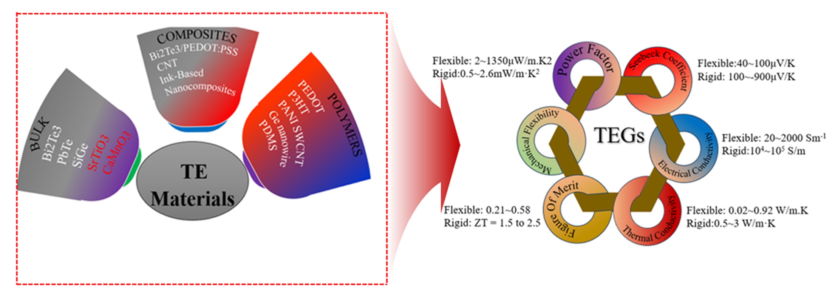


Fig. 1.
Fig. 2.
Fig. 3.
Fig. 4.
Fig. 5.
Fig. 6.
Fig. 7.
Fig. 8.
Fig. 9.
Graphical abstract
| Material | Type | ZT | T (K) | σ (Sm-1) | S (μVK-1) | S2σ (Wm-1K-2) | k (W m–1K–1) | Ref. |
|---|---|---|---|---|---|---|---|---|
| Bi2Te3 nanoplates | n | 0.62 | 400 | 6.3×10⁻⁴ | 160 | 12×10-4 | 0.37 | [16] |
| Bi2Te3-xSex | n | 1.23 | 480 | 4.7×10⁻⁴ | 198 | 19×10-4 | 0.98 | [17] |
| Bi2Te2.7Se0.3 +La2O3 | n | 0.97 | 455 | 4×10⁻⁴ | 170 | 20×10-4 | 1.05 | [18] |
| Bi2Te2.7Se0.3/h-BN composites | n | 1.1 | 400 | 1434 | 988 | 31×10-4 | 0.42 | [19] |
| Sb2Te3(GeTe)17 | p | 2.4 | 773 | 692 | 255 | 45 | 1.40 | [26] |
| Ge0.95Sb0.05Te1.025 | p | 2.4 | 773 | 785 | 255 | 51 | 1.60 | [27] |
| Ge0.9Sb0.1In0.01Te | p | 2.3 | 800 | 444.4 | 262.5 | 30.6 | 1.10 | [28] |
| Materials | σ (Scm-1) | S (µV K−1) | S2σ (μ Wm−1 K-2) | Ref. |
|---|---|---|---|---|
| PEDOT:PSS | 2170 | 39.2 | 334 | [33] |
| SnS/PPy | 32.26 | 50.67 | 6 | [37] |
| ZB-A/PAn/PSS | 2.1 | 80 | 664 | [30] |
| ZIF-67@CNT | 825.7 | 54 | 242 | [31] |
| PANI/Co-MOF-Br | 4.8×10⁻² | 46.3 | 66 | [32] |
| MOF M-UiO-66, EG-PEDOT and SWCNTs | 486.3 | 17.9 | 27.9 | [36] |
| Ag-Te NWs/ PEDOT:PSS | 463 | 69.5 | 224 | [38] |
Table 1.
Table 2.
TOP
