Warning: mkdir(): Permission denied in /home/virtual/lib/view_data.php on line 81

Warning: fopen(upload/ip_log/ip_log_2024-11.txt): failed to open stream: No such file or directory in /home/virtual/lib/view_data.php on line 83

Warning: fwrite() expects parameter 1 to be resource, boolean given in /home/virtual/lib/view_data.php on line 84
Development of Powder Injection Molding Process for Fabrication of Glass Component
Skip Navigation
Skip to contents

Journal of Powder Materials : Journal of Powder Materials

OPEN ACCESS
SEARCH
Search

Articles

Page Path
HOME > J Korean Powder Metall Inst > Volume 23(1); 2016 > Article
Article
Development of Powder Injection Molding Process for Fabrication of Glass Component
Dongguo Lin, Junghyun Leea, Seong Jin Park*
Journal of Korean Powder Metallurgy Institute 2016;23(1):26-32.
DOI: https://doi.org/10.4150/KPMI.2016.23.1.26
Published online: January 31, 2016

Department of Mechanical Engineering, Pohang University of Science and Engineering (POSTECH), Pohang 790-784, Korea

a GTC, Samsung Electronics Co., Ltd., Suwon 443-742, Korea

* Corresponding Author: Seong Jin Park, TEL: +82-54-279-2182, FAX: +82-54-279-5899, E-mail: sjpark87@postech.ac.kr
• Received: November 2, 2015   • Revised: December 14, 2015   • Accepted: December 17, 2015

© The Korean Powder Metallurgy Institute. All rights reserved.

  • 740 Views
  • 7 Download
  • 8 Crossref
prev next
  • Powder injection molding (PIM), which combines the advantages of powder metallurgy and plastic injection molding technologies, has become one of the most efficient methods for the net-shape production of both metal and ceramic components. In this work, plasma display panel glass bodies are prepared by the PIM process. After sintering, the hot isostatic pressing (HIP) process is adopted for improving the density and mechanical properties of the PIMed glass bodies. The mechanical and thermal behaviors of the prepared specimens are analyzed through bending tests and dilatometric analysis, respectively. After HIPing, the flexural strength of the prepared glass body reaches up to 92.17 MPa, which is 1.273 and 2.178 times that of the fused glass body and PIMed bodies, respectively. Moreover, a thermal expansion coefficient of 7.816 × 10⁻⁶/°C is obtained, which coincides with that of the raw glass powder (7.5-8.0 × 10⁻⁶/°C), indicating that the glass body is fully densified after the HIP process.
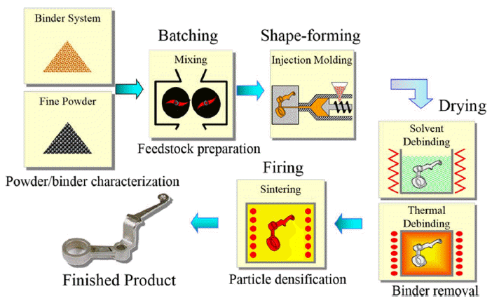
Powder injection molding (PIM) is a productive and widely used technique for net-shaping metal and ceramic components. This technique combines the advantages of both plastic injection molding technology and traditional powder metallurgy technology, producing high performance component, tight tolerance, shape complexity and low production cost [1]. Due to these advantages, PIM is applicable to various uses, such as mechanical components, biomedical components, etc. As shown in Fig. 1, there are four main steps in PIM process, which are mixing, injection molding, debinding, and sintering. In this research, we aimed to find the way to manufacturing glass components using commercial glass powder through PIM process.
Fig. 1

Schematic diagram of PIM process.

KPMI-23-1-26_F1.gif
The definition of glass in ASTM is that an inorganic product of fusion which has been cooled to a rigid condition without crystallization. Also glass is an amorphous solid material which is typically brittle and optically transparent [2]. Nowadays, glass becomes an essential material for human beings, which can be found everywhere. In addition, the application range of glass becomes wider and wider, which includes daily supplies, architecture, medical devices, chemistry, electrics, instruments and nuclear engineering, etc. As the daily developing of technologies and increasing demand of people, more and more special glass component with complex shape, high performances and energy-saving process are required.
People usually prepare glass components by melting the glass into liquid and cooling it to get final product. The processes always includes preprocess for raw material, preparation of batch, founding, molding and heat treatment [2]. However, fabricating glass components by sintering also becomes a hot issue today. Sintering is a thermal treatment for bonding the particles into a coherent, solid mass based on atomic diffusion. Sintering densification usually occurs close to the melting temperature for the material. The bonds between particles grow by the motion of individual atoms via either solid-state or liquid-phase events [1]. Since the sintering temperature for materials always shows out lower than their melting point, it is often chosen as the shaping process for many ceramic materials especially which with high melting points.
Glass also can be fabricated with sintering instead of traditional fusing method and lots of related researches have been carried out [3-10]. Fabricating glass by sintering allows formation for complex shapes and reduction of technological temperature. Also, sintering technology gives a high level of purity and uniformity in starting materials and a capability to produce nearly net-shaped glass objects in simper subsequent process.
The plasma display panel (PDP) glass is a very important material to manufacture the displays, which can be found everywhere in today’s human life and industries. The plasma displays are usually brighter than other types of displays and have a wide color gamut because it has the small cells containing the electrically charged ionized gases working in plasma display. Through studying on the manufacturing of PDP glass by sintering, a manufacturing method under a low temperature, the advantages from operating at lower temperature can be achieved and wider industrial applications for sintered glass components can be expanded.
In this study, the PIM process has been developed to fabricate the PDP glass bodies. The glass compacts were prepared by the press-sinter route using pressureless sintering. After sintering, hot isostatic pressing (HIP) process was carried out as a post-process aimed at improving the density and mechanical properties of PIMed glass bodies. Also, the mechanical properties and thermal expansion coefficient of prepared samples were characterized.
2.1. Materials
The glass powder used in this research is PDP powders with main composition of SiO2-B2O3-Al2O3. This powder has a mean particle size of 2.37 μm, melting point of 919°C and thermal expansion coefficient of (80 ± 5) × 10−7/°C. The morphology of this powder is shown in Fig. 2, which was observed under a scanning electron microscope (SEM). The powder was produced by milling process, which showed an irregular shape with a relatively wide particle size distribution. The apparent density, tap density and pycnometer density for the powder were measured showing the value of 0.72 g/cm3, 0.98 g/cm3, and 2.87 g/cm3 in sequence.
Fig. 2

The images of PDP glass powder: (a) As-received powder image, (b) SEM image.

KPMI-23-1-26_F2.gif
A wax-polymer binder system consisting of paraffin wax (PW), polypropylene (PP), polyethylene (PE) and stearic acid (SA) was used. The thermal properties of binder system can play important role to total PIM process. The physical properties of each binder component were listed in Table 1.
Table 1

Physical properties of binders

Property PW PP PE SA

Density (g/cm3) 0.92 0.92 0.93 0.95
Melting temperature (°C) 51 78 120 53
Decomposition temperature (°C) 242-280 464-481 464-471 246-275
2.2. Experimental procedure

2.2.1. Mixing

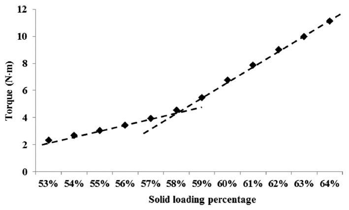
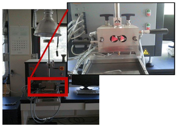
In order to get a homogeneous mixture of powders and binders, besides powder characteristics and binder composition, the ratio of powder to binder is also important. Too little binder results in a high viscosity and trapped air pockets that make for molding difficulties. On the contrary, excess binder separates from the powder in molding, leading to flashing or inhomogeneity in the molded part [1]. In this work, torque rheometer experiment was carried out to find out the critical solid loading percentage. The powder and binders were mixed in a twin-screw mixing chamber (see Fig. 3) at a temperature of 150°C and a mixing speed of 150 rpm. The glass powder was added into the fixed amount of binders with an increment of 1 vol.% of solid loading and the mixing torque was recorded. The procedure was repeated until the mixing torque rapidly increased, which represented the critical solid loading point. Considering the flexibility in PIM process, the optimal solid loading was selected as 2 vol.% lower than critical solid loading point.
Fig. 3

Torque rheometer with twin-screw mixing chamber.

KPMI-23-1-26_F3.gif
After determining the optimal solid loading, the mixing process was carried out using a twin-screw extruder type mixer under the mixing speed of 30 rpm, mixing temperature of 150°C, and optimal powder loading of 56 vol.%. The same mixing procedure was performed three times to ensure the homogeneity of feedstock.

2.2.2. Injection molding

The mixed feedstock was injection molded into 3-point bending specimens using a PIM specialized injection molding machine which had a maximum clamping force of 30 ton. The injection molding was performed under 10 mm/s of injection speed, 600 kg/cm2 of injection pressure, 160°C of injection temperature and 35°C of mold temperature.

2.2.3. Debinding

Debinding is always done before sintering, since the binder becomes a disposable component after molding. In this research, in order to totally remove the binder, both solvent debinding and thermal debinding were performed to remove the PW and backbone polymers (PP and PE) in sequence. Solvent debinding process was carried out in 60°C n-hexane acid bath for 12 hours.
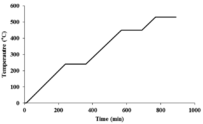
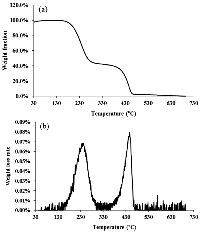
Before thermal debinding, in order to find out the optimal debinding cycle, thermal gravity analysis (TGA) was performed from 30°C to 700°C with heating rate of 5°C/ min under 50 ml/min purged high purity argon gas. Regarding to the TGA result, the debinding cycle was determined as shown in Fig. 4. A slow heating rate of 1°C/min was selected and it was held at 240°C, 450°C, and 530°C for 2 hours, respectively. Also, the high purity argon gas was continuously flowed with a flow rate of 1.5 L/min to sweep the vaporized binders. The weight loss after solvent and thermal debinding was carefully recorded to measure the amount of debound binders.
Fig. 4

Temperature profile for thermal debinding.

KPMI-23-1-26_F4.gif

2.2.4. Sintering and HIP

The debound sample was sintered at 700°C for 2 hours with a heating rate of 2°C /min in oxygen atmosphere using a tube-type atmospheric sintering furnace. In order to improve the density and mechanical properties of sintered glass body, HIP was carried out as the post process. The sintered glass body was HIPed at 700°C for 3 hours with a pressure of 80 MPa in argon atmosphere.

2.2.5. Sample characterization

The mechanical properties of both PIMed and HIPed glass samples were tested through 3-point bending tests, and their flexural strength was compared to study the effect of HIP process on improving the physical properties of sintered sample. The thermal expansion coefficient of HIPed sample was measured through the dilatometry experiment. Firstly, the sample was heated to 400°C by a heating rate of 5°C/min, then it was cooled from 400°C to room temperature by a cooling rate of 5°C /min. The shrinkage occurred during cooling stage was recorded. By fitting the relationship between temperature and shrinkage the thermal expansion for HIPed sample was achieved.
3.1. Determination of critical solid loading
Fig. 5 showed the increment of stabilized torque value at different solid loadings ranging from 53 to 64 vol.%. At first, the torque increased slightly with increasing of powder loading, then after the solid loading reached 58 vol.%, the torque increased rapidly with increasing of powder loading indicating the critical solid loading point was 58 vol.%. In PIM, usually the optimal loading is approximately 2 to 5 vol.% lower than critical one. This reflects the need for process flexibility and recognizes the reality of lot-to-lot variations in powders and binders [1]. In this work, the optical solid loading is set 2 vol.% below the critical one with value of 56 vol.%.
Fig. 5

The torque of glass feedstock at different solid loading percentage.

KPMI-23-1-26_F5.gif
3.2. Binder removal in debinding process
A two-step debinding method, including solvent debinding and thermal debinding, was performed. The filler binder (PW) was firstly removed by solvent debinding, then the thermal debinding was followed to easily remove the residual filler binder and backbone binders (PP and PE) through the open pores and channels formed after solvent debinding process.
Table 2 showed the weight loss of PW before and after solvent debinding. It indicated that totally 86% of PW was debound after 12 hours’ bath in solvent, and the residual 14 % of PW would be removed during thermal debinding.
Table 2

Weight loss after solvent debinding

Injection molded Solvent debound Debound PW

Mass (g) 2.92 2.58 0.34 (86 % of total PW)
To study the binder decomposition behavior during thermal debinding process, the TGA experiment for prepared glass feedstock has been carried out. Fig. 6(a) showed the weight loss of prepared glass feedstock as temperature increasing from 30 to 700°C. There were two sigmoids decomposition function showing the binders were removed by two stages. The first sigmoid was related to the decomposition of filler binder (PW and SA), which had a relatively lower decomposition temperature, and the second sigmoid was related to the decomposition of backbone binder (PP and PE), which had a relatively higher decomposition temperature. Fig. 6(b) showed the weight loss rate of prepared glass feedstock. The maximum weight loss rate for first and second sigmoid occurred at 236 and 446°C, respectively. According to this, the holding temperatures during thermal debinding process were determined at the slightly higher temperature of 240 and 450°C, respectively, to fully remove the remained filler binder and backbone binder in injection molded parts.
Fig. 6

TGA results for prepared glass feedstock: (a) Weight loss, (b) Weight loss rate.

KPMI-23-1-26_F6.gif
Table 3 showed the weight loss of binder after thermal debinding process. It indicated that almost all binder (99.6% of total binder) has been removed successfully by two-step debinding process, which was one of the most important point in glass PIM process to get a translucent/ transparent glass component.
Table 3

Weight loss after thermal debinding

Injection molded Solvent debound Thermal debound Debound binder

Mass (g) 2.92 2.58 2.28 0.64 (99.6 % of total binder)
3.3. Sample characterization

3.3.1. Physical property

After sintering at 700°C for 2 hours in oxygen atmosphere, the relative density of sintered glass body was 92%, which was a relatively low value mainly due to the poor sinter-ability of glass powders. However, after HIP treatment, the density of HIPed glass body was increased from 92% to 98%. Fig. 7(a) and (b) showed the microstructures of cross-section of sintered and HIPed samples observed by optical microscope. Some large and small round pores existed after sintering leading to a low sintered density. After HIP process, the sintered body was furtherly densified, where the pores were largely eliminated and pore size became much smaller.
Fig. 7

Microstructures of cross-section of fabricated glass samples: (a) Sintered body, (b) Sinter-HIPed body.

KPMI-23-1-26_F7.gif

3.3.2. Mechanical property

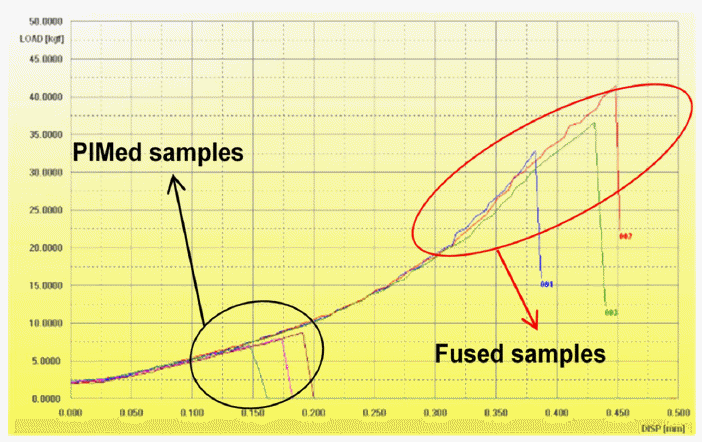
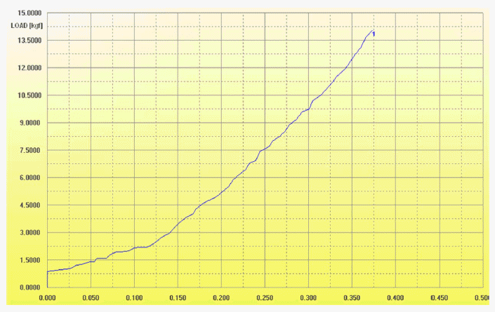
The mechanical property of PIMed glass body was evaluated by 3-point bending test. The result was compared to that of fused glass body which is the traditional way to make glass component. The process for making fused glass was that melting the glass powder under 1200°C and cooling to room temperature in air. Fig. 8 showed the results of bending tests of PIMed and fused glass samples. It showed that the average flexural strength for PIMed and fused glass samples were 42.31 MPa and 72.42 MPa, respectively. The main reason for lower strength of PIMed sample was that more pores existed in sintered sample (Fig. 7(a)) which lead to easier crack produce and propagation resulting in lower bending strength. However, after HIP treatment, the flexural strength increased to 92.17 MPa (Fig. 9), which was 1.273 times (127.3%) of the fused glass samples and 2.178 times (217.8%) of PIMed samples without HIP process.
Fig. 8

Results of bending test for PIMed and fused samples (load vs. displacement).

KPMI-23-1-26_F8.gif
Fig. 9

Results of bending test for PIM-HIPed sample (load vs. displacement).

KPMI-23-1-26_F9.gif

3.3.3. Thermal expansion coefficient

Thermal property is one of the most important for glass components. When a glass is heated, it generally expands. If the temperature over the body of glass is equal everywhere and the body is not restrained, then there will be no development of stress in the body. On the other hand, there were non-uniform heating over the body, and then the different layers of glass would attempt to expand differently. The enforcement of the compatibility criteria results in a different set of dimensional changes and stresses develop. The tensile stress components could lead to glass failure [2].
Linear thermal expansion was measured using a pushrod dilatometer in this work. Based on the definition of linear thermal expansion coefficient, the thermal expansion coefficient αL can be calculate by the equation as below:
(1)
αL=ΔLLΔT
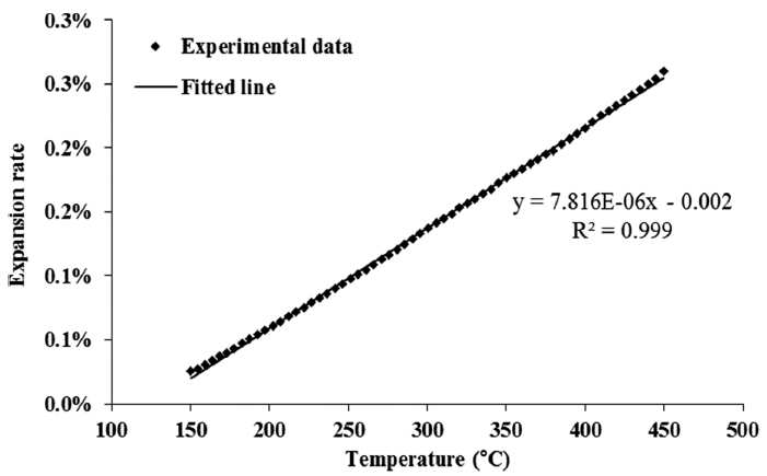
In Eq. (1), αL means linear thermal expansion coefficient, ΔL means the change of length, L means the initial length and ΔT means the change of temperature. For calculating the thermal expansion coefficient of sinter- HIPed glass samples, data from 450~150°C in cooling process was used for analyzing the coefficient. Also, as we can see in Eq. (1), ΔL/L means the shrinkage rate, so the value of linear thermal expansion coefficient can be calculate as the slope of temperature vs. shrinkage. By fitting the data from 450~150°C the coefficient was calculated as shown in Fig. 10. The fitted value was 7.82 × 10⁻⁶/°C, which matched well with the thermal coefficient of raw glass powder provided by the powder vendor (7.5~8.0 × 10⁻⁶/°C) indicating by PIM-HIP process the glass body was almost fully densified and the manufacturing process was reasonable.
Fig. 10

Thermal expansion coefficient of fabricated glass sample.

KPMI-23-1-26_F10.gif
The PDP glass component has been fabricated by PIM technology using a wax-polymer binder system. The PIM process has been developed and optimized including determination of optimal solid loading and debinding conditions. The relative density for sintered glass body was 92%, however, after HIP treatment it increased to 98%. The flexural strength for PIMed was 42.31 MPa, and it increased to 92.17 MPa after HIP treatment, which was 1.273 times of the fused glass sample (72.42 MPa). The thermal expansion coefficient of fabricated glass sample was 7.816 × 10⁻⁶/°C, a value matched well with the thermal coefficient of raw powder (7.5~8.0 × 10⁻⁶/°C) indi- cating that the glass body was well fabricated by PIMHIP process with the proper processing conditions.
Acknowledgements
This research was supported by the National Research Foundation of Korea (NRF) grant funded by the Korea government (MSIP) (No. 2011-0030075).
  • 1. R. M. German and A. Bose: Injection Molding of Metals and Ceramics, Metal Powder Industries Federation, New Jersey (1997).
  • 2. Arun K. Varshneya: Fundamentals of Inorganic Glasses, New York State College of Ceramics Alfred University & Saxon Glass Technologies, Inc., New York (2006).
  • 3. D. Lin, S. Yi, J. Heo, J. Lee, R. M. German and S. J. Park: Ceram. Int., 41 (2015) 5057. Article
  • 4. E. M. Rabinovich: J. Mater. Sci., 20 (1985) 4259. Article
  • 5. H.-N. Choi and Y.-S. Kim: Microsyst. Technol., 11 (2005) 404. Article
  • 6. D. Hiratsuka, J. Tatami, T. Wakihara, K. Komeya and T. Meguro: J. Ceram. Soc. Jpn., 115 (2007) 392. Article
  • 7. J. Zhang, R. Tu and T. Goto: Ceram. Int., 38 (2012) 4961. Article
  • 8. L. H. Wang and B. J. Tsai: Mater. Lett., 43 (2000) 309. Article
  • 9. S.-L. Fu, L.-S. Chen and J.-H. Chou: Ceram. Int., 20 (1994) 67. Article
  • 10. O. Yong-Taeg, S. Fujino and K. Morinaga: Sci. Technol. Adv. Mater., 3 (2002) 297.Article

Figure & Data

References

    Citations

    Citations to this article as recorded by  
    • Fabrication and characteristics of Li2TiO3 pebbles manufactured by using powder injection molding (PIM) process
      Young Ah Park, Yi-Hyun Park, Mu-Young Ahn, Young Soo Yoon
      Journal of Nuclear Materials.2024; 597: 155140.     CrossRef
    • Combined simulation of micro and nanoparticles in RF inductively coupled plasma torches with the variations of metallic species and feeding nozzle location
      Cheongbin Cheon, Ho Jun Kim, Hae June Lee
      Japanese Journal of Applied Physics.2023; 62(SA): SA1014.     CrossRef
    • High-throughput injection molding of transparent fused silica glass
      Markus Mader, Oliver Schlatter, Barbara Heck, Andreas Warmbold, Alex Dorn, Hans Zappe, Patrick Risch, Dorothea Helmer, Frederik Kotz, Bastian E. Rapp
      Science.2021; 372(6538): 182.     CrossRef
    • Controlling the sintering response in the development of multilayered components produced via powder injection molding route—a review
      O. J. Ojo-kupoluyi, S. M. Tahir, T. T. Dele-Afolabi, M. S. Anuar
      The International Journal of Advanced Manufacturing Technology.2020; 107(9-10): 3755.     CrossRef
    • Fabrication of pressureless sintered Si3N4 ceramic balls by powder injection molding
      Chang Woo Gal, Gi Woung Song, Woon Hyung Baek, Hyung Kyu Kim, Dae Keun Lee, Ki Wook Lim, Seong Jin Park
      Ceramics International.2019; 45(5): 6418.     CrossRef
    • Thermal decomposition behavior and modeling of PMN-PZT ceramic feedstock with varying binder compositions
      Jae Man Park, Jun Sae Han, Chang Woo Gal, Joo Won Oh, Dongguo Lin, Jaebum Noh, Kunal H Kate, Sundar V Atre, Youngmoo Kim, Seong Jin Park
      Materials Research Express.2019; 6(6): 065316.     CrossRef
    • Powder Injection Molding Process in Industrial Fields
      Joo Won OH, Chang Woo GAL, Daseul SHIN, Jae Man PARK, Woo Seok YANG, Seong Jin PARK
      Journal of the Japan Society of Powder and Powder Metallurgy.2018; 65(9): 539.     CrossRef
    • Optimization of Process Condition for Fe Nano Powder Injection Molding
      Joo Won Oh, Won Sik Lee, Seong Jin Park
      Journal of Korean Powder Metallurgy Institute.2017; 24(3): 223.     CrossRef

    • PubReader PubReader
    • Cite this Article
      Cite this Article
      export Copy Download
      Close
      Download Citation
      Download a citation file in RIS format that can be imported by all major citation management software, including EndNote, ProCite, RefWorks, and Reference Manager.

      Format:
      • RIS — For EndNote, ProCite, RefWorks, and most other reference management software
      • BibTeX — For JabRef, BibDesk, and other BibTeX-specific software
      Include:
      • Citation for the content below
      Development of Powder Injection Molding Process for Fabrication of Glass Component
      J Korean Powder Metall Inst. 2016;23(1):26-32.   Published online February 1, 2016
      Close
    • XML DownloadXML Download
    Figure
    • 0
    • 1
    • 2
    • 3
    • 4
    • 5
    • 6
    • 7
    • 8
    • 9
    Related articles
    Development of Powder Injection Molding Process for Fabrication of Glass Component
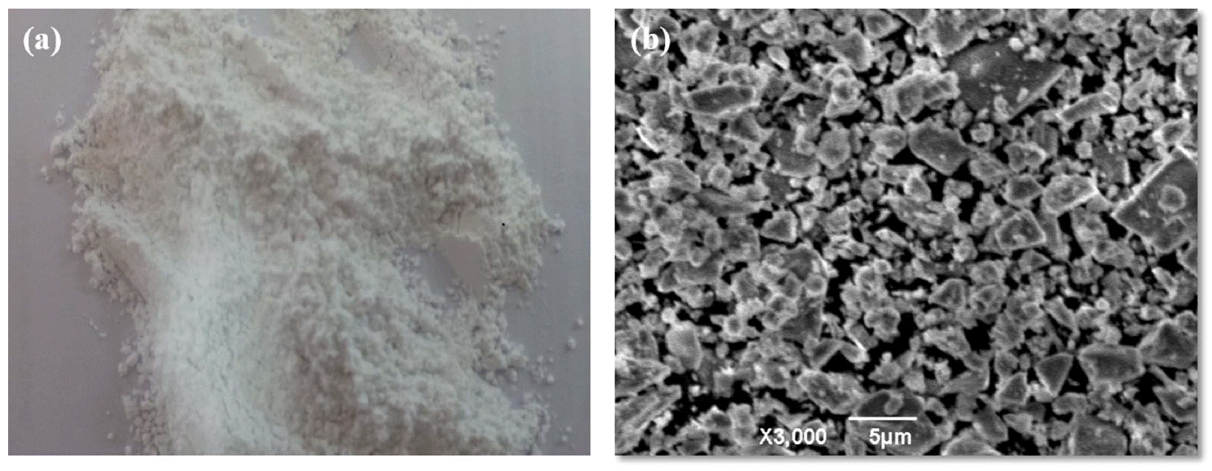
    Image Image Image Image Image Image Image Image Image Image
    Fig. 1 Schematic diagram of PIM process.
    Fig. 2 The images of PDP glass powder: (a) As-received powder image, (b) SEM image.
    Fig. 3 Torque rheometer with twin-screw mixing chamber.
    Fig. 4 Temperature profile for thermal debinding.
    Fig. 5 The torque of glass feedstock at different solid loading percentage.
    Fig. 6 TGA results for prepared glass feedstock: (a) Weight loss, (b) Weight loss rate.
    Fig. 7 Microstructures of cross-section of fabricated glass samples: (a) Sintered body, (b) Sinter-HIPed body.
    Fig. 8 Results of bending test for PIMed and fused samples (load vs. displacement).
    Fig. 9 Results of bending test for PIM-HIPed sample (load vs. displacement).
    Fig. 10 Thermal expansion coefficient of fabricated glass sample.
    Development of Powder Injection Molding Process for Fabrication of Glass Component
    Property PW PP PE SA

    Density (g/cm3) 0.92 0.92 0.93 0.95
    Melting temperature (°C) 51 78 120 53
    Decomposition temperature (°C) 242-280 464-481 464-471 246-275
    Injection molded Solvent debound Debound PW

    Mass (g) 2.92 2.58 0.34 (86 % of total PW)
    Injection molded Solvent debound Thermal debound Debound binder

    Mass (g) 2.92 2.58 2.28 0.64 (99.6 % of total binder)
    Table 1 Physical properties of binders

    Table 2 Weight loss after solvent debinding

    Table 3 Weight loss after thermal debinding


    Journal of Powder Materials : Journal of Powder Materials
    TOP